Emerson Rosemount 485 Annubar Quick Installation Manual
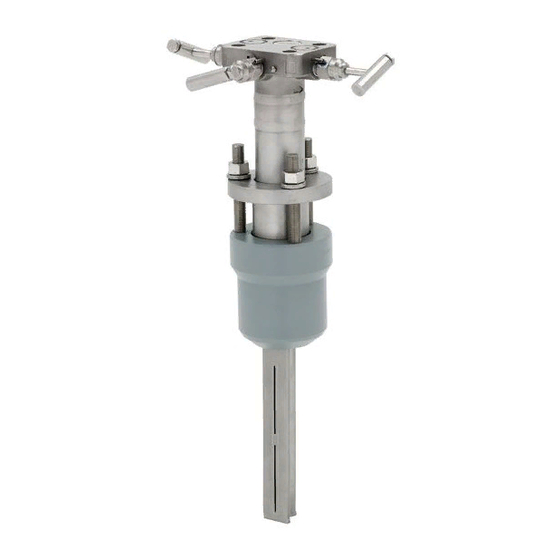
Flange-lok assembly
Hide thumbs
Also See for Rosemount 485 Annubar:
- Quick start manual (36 pages) ,
- Quick installation manual (21 pages) ,
- Reference manual (98 pages)
Table of Contents
Advertisement
Quick Links
Quick Installation Guide
00825-0200-4809, Rev CA
September 2003
Rosemount 485 Annubar
Flange-Lok Assembly
®
HART
¢00825-0200-4809c¤
www.rosemount.com
Step 1: Location and Orientation
Step 2: Drill Hole into Pipe
Step 3: Weld Mounting Hardware
Step 4: Insert the Annubar
Step 5: Mount the Transmitter
Flange-Lok 485 Annubar
®
Advertisement
Table of Contents

Related Manuals for Emerson Rosemount 485 Annubar


Summary of Contents for Emerson Rosemount 485 Annubar
- Page 1 Quick Installation Guide 00825-0200-4809, Rev CA Flange-Lok 485 Annubar September 2003 ® Rosemount 485 Annubar Flange-Lok Assembly Step 1: Location and Orientation Step 2: Drill Hole into Pipe Step 3: Weld Mounting Hardware Step 4: Insert the Annubar Step 5: Mount the Transmitter ®...
-
Page 2: Important Notice
Quick Installation Guide 00825-0200-4809, Rev CA Flange-Lok 485 Annubar September 2003 © 2003 Rosemount Inc. All rights reserved. All marks are the property of their owners. Emerson Process Management Rosemount Inc. GmbH & Co. OHG 8200 Market Boulevard Chanhassen, MN USA 55317... - Page 3 Quick Installation Guide 00825-0200-4809, Rev CA Flange-Lok 485 Annubar September 2003 ® 485 Annubar Flange-Lok Assembly Exploded View Transmitter and housing are shown Transmitter for clarity purposes – only supplied if ordered. Coplanar Flange with Drain Vents O-Rings (2) Direct Mount Electronics Connection with Valves Follower Compression Plate...
- Page 4 Quick Installation Guide 00825-0200-4809, Rev CA Flange-Lok 485 Annubar September 2003 1: L OCATION AND RIENTATION Correct orientation and straight run requirements must be met for accurate and repeatable flow measurements. Refer to Table 1 for minimum pipe diameter distances from upstream disturbances. Table 1.
- Page 5 Quick Installation Guide 00825-0200-4809, Rev CA Flange-Lok 485 Annubar September 2003 CONTINUED Upstream Dimensions Without Vanes With Vanes Out of Plane A Plane A A’ C’ — — — — — — — — — — — — — — —...
- Page 6 Quick Installation Guide 00825-0200-4809, Rev CA Flange-Lok 485 Annubar September 2003 CONTINUED NOTE • For gas service, multiply values from Table 1 by 1.5. • Consult the factory for instructions regarding use in square or rectangular ducts. • “In Plane A” means the bar is in the same plane as the elbow. “Out of Plane A”...
-
Page 7: Horizontal Orientation
Quick Installation Guide 00825-0200-4809, Rev CA Flange-Lok 485 Annubar September 2003 CONTINUED Horizontal Orientation For proper venting and draining, the sensor should be located in the upper half of the pipe for air and gas applications. For liquid and steam applications, the sensor should be located in the bottom half of the pipe. - Page 8 Quick Installation Guide 00825-0200-4809, Rev CA Flange-Lok 485 Annubar September 2003 CONTINUED Vertical Orientation The sensor can be installed in any position around the circumference of the pipe provided the vents are positioned properly for bleeding or venting. Optimal results for liquid or steam are obtained when flow is up.
- Page 9 Quick Installation Guide 00825-0200-4809, Rev CA Flange-Lok 485 Annubar September 2003 2: D RILL 1. Determine the sensor size based on the probe width (see Table 2). 2. Depressurize and drain the pipe. 3. Select the location to drill the hole. 4.
-
Page 10: Step 3: Weld Mounting Hardware
Quick Installation Guide 00825-0200-4809, Rev CA Flange-Lok 485 Annubar September 2003 3: W OUNTING ARDWARE 1. Center the flanged assembly over the mounting hole, gap (1.5 mm), and measure the distance from the outer diameter of the pipe to the face of the flange. Compare this to Table 3 and adjust the gap as necessary. - Page 11 Quick Installation Guide 00825-0200-4809, Rev CA Flange-Lok 485 Annubar September 2003 CONTINUED Figure 7. Alignment Tack Welds 3. If opposite side support is being used, center the fitting for the opposite side support over the opposite side hole, gap -in. (1.5 mm), and place four -in.
- Page 12 Quick Installation Guide 00825-0200-4809, Rev CA Flange-Lok 485 Annubar September 2003 4: I NSERT THE NNUBAR 1. Align the flow arrow on the head with the direction of flow. Assembly the bar to the mounting flange using a gasket, bolts, and nuts. 2.
- Page 13 Quick Installation Guide 00825-0200-4809, Rev CA Flange-Lok 485 Annubar September 2003 CONTINUED 10. Tighten the nuts onto the studs: a. Place the included split-ring lock washer between each of the nuts and the compression plate. Give each nut one half turn in succession until the split-ring lock washer is flat between the nut and the compression plate.
- Page 14 Quick Installation Guide 00825-0200-4809, Rev CA Flange-Lok 485 Annubar September 2003 CONTINUED Figure 8. Packing Ring Detail Compression Plate Retaining Ring Follower Packing Rings (3) Figure 9. Split-Ring Lock Washer Orientation Before After Tightening Tightening NOTE Flange-Lok sealing mechanisms generate significant force at the point where the sensor contacts the opposite pipe wall.
-
Page 15: Mount The Transmitter
Quick Installation Guide 00825-0200-4809, Rev CA Flange-Lok 485 Annubar September 2003 5: M OUNT THE RANSMITTER Transmitter Mounting, Direct Mount Head with Valves It is not necessary to retract the Annubar when direct mounting a transmitter with valves. ® 1. Place Teflon (PTFE) O-rings into grooves on the face of head. - Page 16 Quick Installation Guide 00825-0200-4809, Rev CA Flange-Lok 485 Annubar September 2003 CONTINUED The following restrictions and recommendations apply to impulse piping location: 1. Impulse piping that runs horizontally must slope at least one inch per foot (83 mm/m). • Slope downward (toward the electronics) for liquid and steam applications •...
- Page 17 Quick Installation Guide 00825-0200-4809, Rev CA Flange-Lok 485 Annubar September 2003 CONTINUED Figure 10. Valve Identification for 5-valve and 3-Valve Manifolds 5-Valve Manifold 3-Valve Manifold To PH To PL To PH To PL Table 4. Description of Impulse Valves and Components Name Description Purpose...
- Page 18 Quick Installation Guide 00825-0200-4809, Rev CA Flange-Lok 485 Annubar September 2003 CONTINUED Recommended Installations Gas Service Secure the electronics above the sensor to prevent condensable liquids from collecting in the impulse piping and the DP cell. Liquid Service (up to 250 °F (121 °C)) Secure the electronics below the sensor to ensure that air will not be introduced into the impulse piping or the electronics.
- Page 19 Quick Installation Guide 00825-0200-4809, Rev CA Flange-Lok 485 Annubar September 2003 CONTINUED Steam or Liquid Service (above 250 °F (121 C)) Mount the electronics below the process piping, adjust 10 to 15 degree above direct vertical down. Route the impulse piping down to the electronics and fill the system with cool water through the two tee fittings.
-
Page 20: Hazardous Locations Certifications
A hard copy may be obtained by contacting our local sales office. European Pressure Equipment Directive (PED) (97/23/EC) Rosemount 485 Annubar — Refer to EC declaration of conformity for conformity assessment Pressure Transmitter — See appropriate Pressure Transmitter QIG...
Need help?
Do you have a question about the Rosemount 485 Annubar and is the answer not in the manual?
Questions and answers