
Subscribe to Our Youtube Channel
Related Manuals for Emerson Rosemount Analytical 400A


Summary of Contents for Emerson Rosemount Analytical 400A
- Page 1 Instruction Manual IM-103-400A, Rev. 1.0 December 2008 Model 400A Hydrocarbon Analyzer http://www.raihome.com...
-
Page 3: Table Of Contents
Instruction Manual IM-103-400A, Rev. 1.0 Model 400A December 2008 Essential Instructions........i SECTION i Preface . - Page 4 Instruction Manual IM-103-400A, Rev. 1.0 Model 400A December 2008 SECTION 3 Initial Startup and Operation ....... . 3-1 Startup and Operation Initial Analyzer Startup .
-
Page 5: Essential Instructions
December 2008 Hydrocarbon Analyzers READ THIS PAGE BEFORE PROCEEDING! ESSENTIAL Emerson Process Management designs, manufactures and tests its products to meet many national and international standards. Because these INSTRUCTIONS instruments are sophisticated technical products, you MUST properly install, use, and maintain them to ensure they continue to operate within their normal specifications. - Page 6 Instruction Manual IM-103-400A, Rev. 1.0 Model 400A December 2008...
-
Page 7: Preface
Instruction Manual IM-103-400A, Rev. 1.0 Model 400A December 2008 Section i Introduction Preface ......... page iii Definitions . -
Page 8: Symbols
1-440-914-1261 In addition to the CSC, you may also contact Field Watch. Field Watch is staffed 24 hours per day, 7 days per week. Field Watch coordinates Emerson Process Management’s field service throughout the U.S. and abroad. Phone: 1-800-654-RSMT (1-800-654-7768) -
Page 9: Component Checklist
Instruction Manual IM-103-400A, Rev. 1.0 Model 400A December 2008 Section 1 Description and Specifications Component Checklist ......page 1-1 Overview . -
Page 10: Overview
Instruction Manual IM-103-400A, Rev. 1.0 Model 400A December 2008 Figure 1-1. Typical System Package 1. Instruction Manual IM-103-400A 2. Model 400A Hydrocarbon Analyzer (analyzer configuration dependent on selected options) 3. Power Cord OVERVIEW The following paragraphs provide the equipment descriptions, operating principles, and specifications for the Model 400A Hydrocarbon Analyzer. -
Page 11: Burner Operation
Instruction Manual IM-103-400A, Rev. 1.0 Model 400A December 2008 To minimize system response time, an internal sample-bypass feature provides high-velocity sample flow through the analyzer. Burner Operation Principal components of the burner are the manifold, burner jet, and the collector. Streams of sample, fuel and air delivered by the analyzer flow system (described later) are routed through internal passages in the manifold and into the interior of the burner (Figure 1-2). -
Page 12: Response To Different Hydrocarbons
Instruction Manual IM-103-400A, Rev. 1.0 Model 400A December 2008 Response to Different Both speed and magnitude of analyzer response are affected by the type of hydrocarbon in the sample. Typical curves of response versus time for various Hydrocarbons hydrocarbons are given in Figure 1-3. Magnitude of the analyzer response to an atom of carbon depends on the chemical environment of this atom in the molecule. -
Page 13: Analyzer Flow System
Instruction Manual IM-103-400A, Rev. 1.0 Model 400A December 2008 Table 1-1. Approximate Effective Carbon Numbers Type of Atom Occurrence *Effective Carbon Number Carbon In Aliphatic Compound +1.00 Carbon In Aromatic Compound +1.00 Carbon In Olefinic Compound +0.95 Carbon n Acetylenic Compound +1.30 Carbon In Carbonyl Radical... -
Page 14: Preamplifier Board
Instruction Manual IM-103-400A, Rev. 1.0 Model 400A December 2008 Figure 1-4. Schematic Flow Diagram Preamplifier Board The ionization current generated by the burner is measured by an electrometer preamplifier board located adjacent to the burner assembly. This small current is amplified and transformed into a signal voltage that is then further amplified by a post amplifier before being converted to a digital display suitable for direct data presentation. - Page 15 Instruction Manual IM-103-400A, Rev. 1.0 Model 400A December 2008 The most sensitive gain range includes a trim adjustment so that inter-range correlation can be obtained over the entire signal span. A buffer signal offering unity gain and noise filtration provide a low output impedance to drive the signal cable and post amplifier circuits on the main circuit board.
-
Page 16: Main Electronics Board
Instruction Manual IM-103-400A, Rev. 1.0 Model 400A December 2008 Main Electronics Board The main electronics board hosts several of the functional circuits and features used in the Model 400A Hydrocarbon Analyzer. A diagram of the board is shown in Figure 1-6. Post Amplifier The post amplifier circuit comprises two amplifiers with various combinations of feedback resistances that are logically selected by the front panel RANGE... - Page 17 Instruction Manual IM-103-400A, Rev. 1.0 Model 400A December 2008 Figure 1-6. Main Electronics Board Diagram...
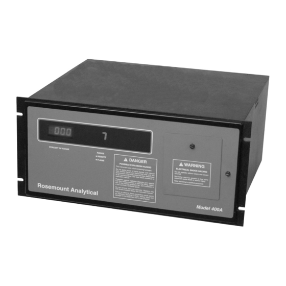
- Page 18 Instruction Manual IM-103-400A, Rev. 1.0 Model 400A December 2008 Figure 1-7. Analyzer Front Panel Display and Controls Digital Displays The voltage originating from the signal amplifiers is made available to output terminals and directly to an analog to digital (A-D) converter for LED data display in digital form.
-
Page 19: Heater Temperature Assembly
Instruction Manual IM-103-400A, Rev. 1.0 Model 400A December 2008 Optically Isolated Remote Range Control To allow for external range control the main electronics board has seven optically isolated digital inputs and one optically isolated digital output. (The digital output is for external range verification.) The external remote range control requires the use of an external (customer supplied) 24 VDC power supply. - Page 20 Instruction Manual IM-103-400A, Rev. 1.0 Model 400A December 2008 Figure 1-8. Analyzer Components Layout and Interconnect Diagram 1-12...
-
Page 21: System Power Supplies
Instruction Manual IM-103-400A, Rev. 1.0 Model 400A December 2008 ± System Power Supplies 12 VDC Used for most analog functions. ± 5 VDC These two voltages derived from a precision reference are used for zero offset and bias requirements. +5 VDC Used to power the digital circuit range decoding A-D display, etc. - Page 22 Instruction Manual IM-103-400A, Rev. 1.0 Model 400A December 2008 The preferred type of fuel depends on the particular application and the characteristics of the sample gas: • For measuring low-level hydrocarbons in ambient air, or in other sample gas with relatively constant oxygen content, 100% hydrogen is preferable.
-
Page 23: Output Options
Instruction Manual IM-103-400A, Rev. 1.0 Model 400A December 2008 Table 1-4. Fuel Gas vs. Analyzer Characteristics 40% H /60% N Analyzer Characteristics 100% H 40%H Full Scale Sensitivity Adjustable from 1 ppm Adjustable from 4 ppm to 2500 ppm CH to 1% CH or 100 ppm to 10% CH Fuel Composition... -
Page 24: Gas Safety Features
Instruction Manual IM-103-400A, Rev. 1.0 Model 400A December 2008 Gas Safety Features The Model 400A is designed to provide a high degree of operational safety. In all analyzers, a front-panel LED indicates that the burner flame is lit. In addition, fuel gas is automatically shut off when a flame-out condition occurs. All tubing ahead of the burner is rigid metallic tubing made up with ferrule/nut type compression fittings. - Page 25 Instruction Manual IM-103-400A, Rev. 1.0 Model 400A December 2008 Specification Feature Sample Gas Requirements Non-Flammable Sample 0.35 to 3.0 liters/minute at 5 to 10 psig (34 to 69 kPa) Flammable Sample 470 cc/minute maximum for safety Burner Air Requirements 350 to 400 cc/minute of zero grade (THC <1 ppm) air, supplied at 25 to 50 psig (172 to 344 kPa) Sample Bypass Flow 0,3 to 3,0 liters/minute...
- Page 26 Instruction Manual IM-103-400A, Rev. 1.0 Model 400A December 2008 Table 1-5. Product Matrix 400A Process Hydrocarbon Analyzer Process Hydrocarbon Analyzer - Instruction Manual Code Seven Ranges with Isolated Remote Range Control and Range Multiplier Seven ranges adjustable between 0-4ppm through 0-1% Seven ranges adjustable between 0-100ppm through 0-10% Seven ranges adjustable between 0-1ppm through 0-2500ppm (Includes 100% H caplillary)
- Page 27 Instruction Manual IM-103-400A, Rev. 1.0 Model 400A December 2008 Section 2 Installation Unpacking ........page 2-2 Location .
-
Page 28: Unpacking
Instruction Manual IM-103-400A, Rev. 1.0 Model 400A December 2008 UNPACKING Carefully examine the shipping carton and contents for signs of damage. Immediately notify the shipping carrier if the carton or its contents are damaged. Retain the carton and packing materials until the instrument is operational. -
Page 29: Fuel And Air Requirements
Instruction Manual IM-103-400A, Rev. 1.0 Model 400A December 2008 Figure 2-1. Mounting Dimensions FUEL AND AIR During normal operation, the analyzer uses fuel and air to maintain the burner flame. Criteria for selection of these gases are defined in the pargraphs that REQUIREMENTS follow. -
Page 30: Air
Instruction Manual IM-103-400A, Rev. 1.0 Model 400A December 2008 NOTE Always make sure the sample flow is present when using the 100% hydrogen fuel option. Absence of sample flow can result in burning of detector tip when using 100% hydrogen. Burner air should be relatively free of hydrocarbons in order to ensure a low background signal. -
Page 31: Gas Connection
Instruction Manual IM-103-400A, Rev. 1.0 Model 400A December 2008 GAS CONNECTION For external gas lines, the use of all new tubing throughout is strongly recommended. Copper refrigeration tubing is preferred. Stainless steel tubing is less desirable; it contains hydrocarbon contaminants, necessitating thorough cleaning before installation. -
Page 32: Leak Check
Instruction Manual IM-103-400A, Rev. 1.0 Model 400A December 2008 Do not perform this operation with the fuel, air and sample lines connected to the analyzer. 5. Recommended method is to attach the tubing to either a nitrogen or helium cylinder through a two-stage regulator and adjust the regulator for a low flow of gas through the tubing. -
Page 33: Electrical Connections
Instruction Manual IM-103-400A, Rev. 1.0 Model 400A December 2008 ELECTRICAL CONNECTIONS Before supplying electrical power to analyzer, complete the gas connections and verify that fuel gas connections are leak free. Do not operate without doors and covers secure. Servicing requires access to live parts which can cause death or serious injury. -
Page 34: Voltage To Current Output Board (Optional)
Instruction Manual IM-103-400A, Rev. 1.0 Model 400A December 2008 Voltage to Current The optional current output in the range of 4 to 20 mA DC appears at terminals mA+ and mA- on the lower barrier strip. Refer to Figure 2-3. This Output Board (Optional) current may be transformed back to a voltage using the appropriate resistor. -
Page 35: Remote Range Id
Instruction Manual IM-103-400A, Rev. 1.0 Model 400A December 2008 Table 2-1. Range Control Terminal Board 24V RET or GND Range 1 Range 2 Range 3 Range 4 Range 5 Range 6 Range 7 When the front panel RANGE MULTIPLIER switch is in the RMT position and an external 24 VDC power supply is properly connected to the analyzer, the REM terminal on the Range ID I/O Board (Figure 2-3) will provide a 24 VDC output with respect to terminal 9 (24V RET) to indicate that the analyzer in the... -
Page 36: Remote Flameout Indication
Instruction Manual IM-103-400A, Rev. 1.0 Model 400A December 2008 Figure 2-4. Remote Flameout Relay Board Remote Flameout Terminals for flameout indication (Control 1 and 2) are shown in Figure 2-4. Whenever the process flame is detected there is no conductive path between Indication Control 1 and Control 2. -
Page 37: Initial Startup And Operation
Instruction Manual IM-103-400A, Rev. 1.0 Model 400A December 2008 Section 3 Startup and Operation Initial Startup and Operation ..... . . page 3-1 Routine Operation . - Page 38 Instruction Manual IM-103-400A, Rev. 1.0 Model 400A December 2008 Figure 3-2. Power Switch 2. Locate the rotary latch on the right-hand side of the front panel. Turn the latch screw counterclockwise to unlatch and open the front panel door. 3. Place the power switch (Figure 3-2) to ON. The front panel display should light up.
- Page 39 Instruction Manual IM-103-400A, Rev. 1.0 Model 400A December 2008 Table 3-1. Internal Pressure Regulator Settings Fuel Gas Internal Pressure 100% H Fuel Mixed Fuel Regulator psig (kPa) psig (kPa) 5 (34) 5 (34) Fuel 25 (172) 30 (207) Sample 5 (34) 0 (0) 8.
-
Page 40: Selection Of Calibration Method And Associated Standard Gas(Es)
Instruction Manual IM-103-400A, Rev. 1.0 Model 400A December 2008 b. Set RANGE switch at 10, SPAN control at 1000 (maximum sensitivity), and ZERO control at 1000 (minimum zero suppression). Approximate full scale sensitivity is now 10 ppm as methane for mixed fuels if the analyzer uses 100% hydrogen fuel, and 40 ppm methane if the analyzer uses mixed fuel. - Page 41 Instruction Manual IM-103-400A, Rev. 1.0 Model 400A December 2008 2. If the analyzer utilizes mixed fuel, an alternative method eliminates the requirement for a special zero gas. Instead, the ZERO control is adjusted with no gas entering the sample inlet. This method is not possible with analyzer utilizing 100% hydrogen fuel, because the burner would overheat.
-
Page 42: Calibration Procedure
Instruction Manual IM-103-400A, Rev. 1.0 Model 400A December 2008 Calibration Procedure After completing the startup procedure calibrate the analyzer according to the instructions that follow. 1. Set downscale calibration point as follows: a. Supply zero gas to sample inlet. Adjust external flow controller or throttle valve so that flow discharge from bypass outlet is between 0.5 and 3.0 liters/minute (preferably between 2.0 and 3.0 liters/minute). - Page 43 Instruction Manual IM-103-400A, Rev. 1.0 Model 400A December 2008 NOTE If the Range multiplier switch is faulty, the front panel will display and "E". If no range is selected when in the remote range mode the front panel will display a lower case "r". If no external power supply is connected to the analyzer, the front panel will display a dash "-".
-
Page 44: Routine Operation
Instruction Manual IM-103-400A, Rev. 1.0 Model 400A December 2008 Example 3 Likewise, after the calibration in example 1, range 1 is automatically calibrated for 8 ppm as 100% full scale. When switching from range 2.5 to 1 (which is 2.5 times more sensitive than 2.5), the display will show 75.0% full scale for 6.0 ppm CH calibration gas (because 75.0% x 8 ppm CH = 6 ppm CH... -
Page 45: Shutdown
Instruction Manual IM-103-400A, Rev. 1.0 Model 400A December 2008 SHUTDOWN Use the following procedure to shut down the Model 400A Hydrocarbon Analyzer. For safety in shutdown, always turn off the fuel gas first, then turn off the air and sample lines. - Page 46 Instruction Manual IM-103-400A, Rev. 1.0 Model 400A December 2008 Figure 3-8. Typical Curves of Analyzer Response vs. Fuel Pressure Regulator Setting Figure 3-9. Typical Curves of Analyzer Response vs. Air Pressure Regulator Setting 3-10...
-
Page 47: General
Instruction Manual IM-103-400A, Rev. 1.0 Model 400A December 2008 Section 4 Troubleshooting General ........page 4-1 System Checkout . -
Page 48: Flame Ignition
Instruction Manual IM-103-400A, Rev. 1.0 Model 400A December 2008 Flame Ignition Start up analyzer per Section 3: Startup and Operation, and attempt to ignite flame. If flame will not ignite refer to Table 4-2, Symptom 2. Noise Check With flame burning, observe indicator or recorder. If noise is greater than 2% of full scale, refer to Table 4-2, Symptom 3. -
Page 49: Thermistor
Instruction Manual IM-103-400A, Rev. 1.0 Model 400A December 2008 Thermistor The thermistor sensor for the FLAME OUT indicator circuit is mounted in the burner. See Figure 1-2. Thermistor resistance should be approximately 100K ohms at 77°F (25°C). An alternate method requires that the comparator input signal be measured at the junction of R32 and R33. - Page 50 Instruction Manual IM-103-400A, Rev. 1.0 Model 400A December 2008 Table 4-2. Analyzer Troubleshooting Symptom Probable Cause Recommended Corrective Action Indicator shows upscale Electrical leakage in burner Clean burner per Section 5, page 5-4. reading when flame is out assembly. Burner will not ignite Fuel gas emerging from burner jet Purge fuel pressure regulator by allowing gas to flow for several minutes, diluted with other gases because...
-
Page 51: Overview
Instruction Manual IM-103-400A, Rev. 1.0 Model 400A December 2008 Section 5 Maintenance and Service Overview ........page 5-1 Amplifier Adjustments . - Page 52 Instruction Manual IM-103-400A, Rev. 1.0 Model 400A December 2008 EXPLOSION HAZARD Do not apply power to analyzer or ignite burner until all leak checks have been performed and until the environment of the analyzer has been determined to be non-hazardous. See Section 2, page 2-6 for the leak check procedure.
-
Page 53: Amplifier Adjustments
Instruction Manual IM-103-400A, Rev. 1.0 Model 400A December 2008 AMPLIFIER Use the following procedures to adjust the amplifier zero level indication and to trim the analyzer signal voltage if needed. ADJUSTMENTS Amplifier Zero Place POWER switch at ON; RANGE switch at 1000; ZERO and SPAN potentiometers at 1000. -
Page 54: Servicing Flow System And Burner
Instruction Manual IM-103-400A, Rev. 1.0 Model 400A December 2008 SERVICING FLOW In preventive maintenance of the flow system, the most important precautions are: 1) provision for continuous removal of all combustion products, including SYSTEM AND BURNER water vapor, and 2) the use of great care to prevent the contamination of any component with hydrocarbons, even in trace amounts. - Page 55 Instruction Manual IM-103-400A, Rev. 1.0 Model 400A December 2008 NOTE All items used for cleaning (tweezers, swabs, etc.) must be absolutely free of contamination. 8. Clean combustion chamber (5), burner tip assembly (7), and chimney assembly (3) with alcohol followed by a distilled water wash. Figure 5-3.
-
Page 56: Burner Reassembly
Instruction Manual IM-103-400A, Rev. 1.0 Model 400A December 2008 Burner Reassembly Using care not to touch internal parts, reassemble burner according to the following procedure. See Figure 5-3. 1. Holding burner tip assembly (7) with clean tissue, screw the assembly finger-tight into manifold (12). -
Page 57: Parts Integrity
Instruction Manual IM-103-400A, Rev. 1.0 Model 400A December 2008 Section 6 Replacement Parts PARTS INTEGRITY Tampering or unauthorized substitution of components may adversely affect safety of this product. Use only factory documented components for repair. CIRCUIT BOARD In most situations involving a malfunction of a circuit board, it is more practical to replace the boar than to attempt isolation and replacement of the individual REPLACEMENT POLICY component. - Page 58 Instruction Manual IM-103-400A, Rev. 1.0 Model 400A December 2008 Table 6-2. Accessories Figure, Item Part Number Description not shown 1101588-002ENG Tag, SS (engraved) 621062 Sample Pump for Model 400A not shown 631118 Kit, Mixed Fuel Acessory not shown 634004 Kit, H Replacement Capillary not shown 655400...
- Page 59 Instruction Manual IM-103-400A, Rev. 1.0 Model 400A December 2008 Figure 6-1. Model 400A Analyzer Assembly - Disassembled View...
-
Page 60: Safety Instructions
Instruction Manual IM-103-400A, Rev. 1.0 Model 400A December 2008 Appendix A Safety Data Safety Instructions ........page A-2 High Pressure Gas Cylinders . - Page 61 Instruction Manual IM-103-400A, Rev. 1.0 Model 400A December 2008...
- Page 62 Instruction Manual IM-103-400A, Rev. 1.0 Model 400A December 2008 IMPORTANT SAFETY INSTRUCTIONS SAFETY INSTRUCTIONS FOR THE WIRING AND INSTALLATION OF THIS APPARATUS The following safety instructions apply specifically to all EU member states. They should be strictly adhered to in order to assure compliance with the Low Voltage Directive.
- Page 63 Instruction Manual IM-103-400A, Rev. 1.0 Model 400A December 2008 DŮLEŽITÉ Bezpečnostní pokyny pro zapojení a instalaci zařízení Následující bezpečnostní pokyny se speciálně vztahují na všechny členské státy EU. Pokyny by měly být přísně dodržovány, aby se zajistilo splnění Směrnice o nízkém napětí. Pokud nejsou pokyny nahrazeny místními či národními normami, měly by je dodržovat i nečlenské...
- Page 64 Instruction Manual IM-103-400A, Rev. 1.0 Model 400A December 2008 VIGTIGT Sikkerhedsinstruktion for tilslutning og installering af dette udstyr. Følgende sikkerhedsinstruktioner gælder specifikt i alle EU-medlemslande. Instruktionerne skal nøje følges for overholdelse af Lavsspændingsdirektivet og bør også følges i ikke EU-lande medmindre andet er specificeret af lokale eller nationale standarder.
- Page 65 Instruction Manual IM-103-400A, Rev. 1.0 Model 400A December 2008 BELANGRIJK Veiligheidsvoorschriften voor de aansluiting en installatie van dit toestel. De hierna volgende veiligheidsvoorschriften zijn vooral bedoeld voor de EU lidstaten. Hier moet aan gehouden worden om de onderworpenheid aan de Laag Spannings Richtlijn (Low Voltage Directive) te verzekeren. Niet EU staten zouden deze richtlijnen moeten volgen tenzij zij reeds achterhaald zouden zijn door plaatselijke of nationale voorschriften.
- Page 66 Instruction Manual IM-103-400A, Rev. 1.0 Model 400A December 2008 BELANGRIJK Veiligheidsinstructies voor de bedrading en installatie van dit apparaat. Voor alle EU lidstaten zijn de volgende veiligheidsinstructies van toepassing. Om aan de geldende richtlijnen voor laagspanning te voldoen dient men zich hieraan strikt te houden. Ook niet EU lidstaten dienen zich aan het volgende te houden, tenzij de lokale wetgeving anders voorschrijft.
- Page 67 Instruction Manual IM-103-400A, Rev. 1.0 Model 400A December 2008 WICHTIG Sicherheitshinweise für den Anschluß und die Installation dieser Geräte. Die folgenden Sicherheitshinweise sind in allen Mitgliederstaaten der europäischen Gemeinschaft gültig. Sie müssen strickt eingehalten werden, um der Niederspannungsrichtlinie zu genügen. Nichtmitgliedsstaaten der europäischen Gemeinschaft sollten die national gültigen Normen und Richtlinien einhalten.
- Page 68 Instruction Manual IM-103-400A, Rev. 1.0 Model 400A December 2008 ΣΗΜΑΝΤΙΚΟ Οδηγιεσ ασφαλειασ για την καλωδιωση και εγκατασταση τησ συσκευησ Οι ακόλουθες οδηγίες ασφαλείας εφαρµόζονται ειδικά για όλες τις χώρες µέλη της Ευρωπαϊκής Κοινότητας. Θα πρέπει να ακολουθούνται αυστηρά ώστε να εξασφαλιστεί η συµβατότητα µε τις οδηγίες για τη Χαµηλή Τάση. Χώρες...
- Page 69 Instruction Manual IM-103-400A, Rev. 1.0 Model 400A December 2008 OLULINE TEAVE Juhtmestiku ja seadme paigaldamisega seotud ohutusjuhised Alljärgnevad ohutusjuhised rakenduvad eriti kõigi Euroopa Liidu liikmesriikide suhtes. Antud juhiseid tuleb täpselt järgida, et kindlustada vastavus madalpinge direktiiviga. Euroopa Liitu mittekuuluvad riigid peavad samuti alljärgnevaid juhiseid järgima, va juhul, kui on olemas vastavad kohalikud riiklikud standardid.
- Page 70 Instruction Manual IM-103-400A, Rev. 1.0 Model 400A December 2008 TÄRKEÄÄ Turvallisuusohje, jota on noudatettava tämän laitteen asentamisessa ja kaapeloinnissa. Seuraavat ohjeet pätevät erityisesti EU:n jäsenvaltioissa. Niitä täytyy ehdottomasti noudattaa jotta täytettäisiin EU:n matalajännitedirektiivin (Low Voltage Directive) yhteensopivuus. Myös EU:hun kuulumattomien valtioiden tulee nou-dattaa tätä...
- Page 71 Instruction Manual IM-103-400A, Rev. 1.0 Model 400A December 2008 IMPORTANT Consignes de sécurité concernant le raccordement et l'installation de cet appareil. Les consignes de sécurité ci-dessous s'adressent particulièrement à tous les états membres de la communauté européenne. Elles doivent être strictement appliquées afin de satisfaire aux directives concernant la basse tension.
- Page 72 Instruction Manual IM-103-400A, Rev. 1.0 Model 400A December 2008 FONTOS Biztonsági előírások a készülék vezetékeléséhez és üzembeállításához A következő biztonsági előírások kifejezetten vonatkoznak az összes EU-tagállamra. Ezeket szigorúan be kell tartani a Kisfeszültségű irányelvnek való megfelelés biztosításához. A nem EU-tagállamok szintén tartsák be a következőket, kivéve ha a helyi és nemzeti szabványok azt másként nem írják elő.
- Page 73 Instruction Manual IM-103-400A, Rev. 1.0 Model 400A December 2008 IMPORTANTE Norme di sicurezza per il cablaggio e l'installazione dello strumento. Le seguenti norme di sicurezza si applicano specificatamente agli stati membri dell'Unione Europea, la cui stretta osservanza è richiesta per garantire conformità...
- Page 74 Instruction Manual IM-103-400A, Rev. 1.0 Model 400A December 2008 SVARBU š io prietaiso laidų prijungimo ir instaliacijos saugos instrukcijos Toliau išvardinti saugumo reikalavimai taikomi konkrečiai visoms ES šalims narėms. Jų turi būti griežtai paisoma, kad būtų užtikrintai laikomasi Žemos įtampos direktyvos. Ne ES narės taip pat turi laikytis toliau pateikiamų...
- Page 75 Instruction Manual IM-103-400A, Rev. 1.0 Model 400A December 2008 SVARĪGI Droš ības norādījumi š īs iekārtas pievienoš anai un uzstādīš anai Turpmākie drošības norādījumi attiecas uz visām ES dalībvalstīm. Tie ir stingri jāievēro, lai nodrošinātu atbilstību Zemsprieguma direktīvai. Turpmāk norādītais jāievēro arī valstīs, kas nav ES dalībvalstis, ja vien šos norādījumus neaizstāj vietējie vai valsts standarti.
- Page 76 Instruction Manual IM-103-400A, Rev. 1.0 Model 400A December 2008 IMPORTANTI STRUZZJONIJIET TAS-SIGURTÀ GĦALL-WIRING U L-INSTALLAZZJONI TAT-TAGĦMIR L-istruzzjonijiet tas-sigurtà japplikaw speċifikament għall-Istati Membri ta' l-UE. Dawn għandhom jiġu osservati b'mod strett biex tkun żgurata l- konformità mad-Direttiva dwar il-Vultaġġ Baxx. Stati li mhumiex membri ta' l-UE għandhom ukoll ikunu konformi ma' dan li ġej ħlief jekk dawn ikunu sostituti mill-Istandards lokali jew Nazzjonali.
- Page 77 Instruction Manual IM-103-400A, Rev. 1.0 Model 400A December 2008 VIKTIG Sikkerhetsinstruks for tilkobling og installasjon av dette utstyret. Følgende sikkerhetsinstruksjoner gjelder spesifikt alle EU medlemsland og land med i EØS-avtalen. Instruksjonene skal følges nøye slik at installasjonen blir i henhold til lavspenningsdirektivet. Den bør også følges i andre land, med mindre annet er spesifisert av lokale- eller nasjonale standarder.
- Page 78 Instruction Manual IM-103-400A, Rev. 1.0 Model 400A December 2008 WAŻNE! Zalecenia dotyczące bezpieczeństwa w zakresie podłączania i instalacji tego urządzenia Następujące zalecenia dotyczą zwłaszcza stosowania urządzenia we wszystkich krajach Unii Europejskiej. Należy się ściśle do nich stosować w celu zapewnienia zgodności z dyrektywą niskonapięciową. W przypadku instalacji urządzenia w krajach nienależących do Unii Europejskiej należy również...
- Page 79 Instruction Manual IM-103-400A, Rev. 1.0 Model 400A December 2008 IMPORTANTE Instruções de segurança para ligação e instalação deste aparelho. As seguintes instruções de segurança aplicam-se especificamente a todos os estados membros da UE. Devem ser observadas rigidamente por forma a garantir o cumprimento da Directiva sobre Baixa Tensão. Relativamente aos estados que não pertençam à...
- Page 80 Instruction Manual IM-103-400A, Rev. 1.0 Model 400A December 2008 DÔLEŽITÉ Bezpečnostné pokyny pre zapojenie káblov a inš taláciu tohto prístroja Nasledovné bezpečnostné pokyny sa vzt’ahujú konkrétne na všetky členské štáty EÚ. Musia byt’ striktne dodržané, aby sa zaistila zhoda so Smernicou o nízkom napätí.
- Page 81 Instruction Manual IM-103-400A, Rev. 1.0 Model 400A December 2008 POMEMBNO Varnostna navodila za povezavo in vgradnjo naprave Naslednja varnostna navodila veljajo za vse države članice EU. Zaradi zagotovitve skladnosti z nizkonapetostno direktivo morate navodila strogo upoštevati. V državah, ki niso članice EU, je treba upoštevati tudi naslednje smernice, razen če jih ne zamenjujejo lokalni ali nacionalnimi standardi.
- Page 82 Instruction Manual IM-103-400A, Rev. 1.0 Model 400A December 2008 IMPORTANTE Instrucciones de seguridad para el montaje y cableado de este aparato. Las siguientes instrucciones de seguridad, son de aplicacion especifica a todos los miembros de la UE y se adjuntaran para cumplir la normativa europea de baja tension.
- Page 83 Instruction Manual IM-103-400A, Rev. 1.0 Model 400A December 2008 VIKTIGT Säkerhetsföreskrifter för kablage och installation av denna apparat. Följande säkerhetsföreskrifter är tillämpliga för samtliga EU-medlemsländer. De skall följas i varje avseende för att överensstämma med Lågspännings direktivet. Icke EU medlemsländer skall också...
- Page 84 Instruction Manual IM-103-400A, Rev. 1.0 Model 400A December 2008 HIGH PRESSURE GAS GENERAL PRECAUTIONS FOR HANDLING AND STORING HIGH PRESSURE GAS CYLINDERS CYLINDERS Edited from selected paragraphs of the Compressed Gas Association's "Handbook of Compressed Gases" published in 1981 Compressed Gas Association 1235 Jefferson Davis Highway Arlington, Virginia 22202 Used by Permission...
- Page 85 If failure was due to conditions listed in the standard Rosemount Analytical warranty, the defective unit will be repaired or replaced at Emerson Process Management's option, and an operating unit will be returned to the customer in accordance with shipping instructions furnished in the cover letter.
- Page 86 Instruction Manual IM-103-400A, Rev. 1.0 Model 400A December 2008...
- Page 87 Instruction Manual IM-103-400A, Rev 1.0 Model 400A December 2008 Index Air Requirements ... 2-4 Heater Temperature Range ID Option ...1-15 Amplifier Zero Adjustment .
- Page 88 Instruction Manual IM-103-400A, Rev 1.0 Model 400A December 2008...
- Page 89 WARRANTY Rosemount Analytical warrants that the equipment manufactured and sold by it will, upon shipment, be free of defects in workmanship or material. Should any failure to conform to this warranty become apparent during a period of one year after the date of shipment, Rosemount Analytical shall, upon prompt written notice from the purchaser, correct such nonconformity by repair or replacement, F.O.B.
- Page 90 Republic of Singapore England T 713 467 6000 T 65 6 777 8211 T 44 1243 863121 F 713 827 3329 F 65 6 777 0947 F 44 1243 845354 E analytical@ ap.emerson.com http://www.raihome.com © 2008 Emerson Process Mangement. All rights reserved.
Need help?
Do you have a question about the Rosemount Analytical 400A and is the answer not in the manual?
Questions and answers