Lutron Electronics Grafik Eye GRX-TVI Installation And Operation Instructions Manual
Control interface
Hide thumbs
Also See for Grafik Eye GRX-TVI:
- Installation and operation instructions manual (48 pages) ,
- Installation and operating instructions (4 pages)
Table of Contents
Advertisement
Available languages
Available languages
Quick Links
Installation and Operation Instructions
Please Read Before Installing
Occupant Copy
Description
The GRX-TVI provides 0-10 V- control and ballast/driver switching
capabilities in one enclosure. The GRX-TVI gives a 100-277 V~
dimmer the ability to control current sourcing 0-10 V- ballasts
or LED drivers (loads) powered by 100-277 V~. The dimmer can
be forward phase,reverse phase, or center phase (for a sample of
approved dimmers, see the list on spec sheet P/N 369247). The
GRX-TVI provides switching relays that can handle the in-rush
current for a circuit of ballasts/drivers. The GRX-TVI can also be
used to switch any of the load types listed below.
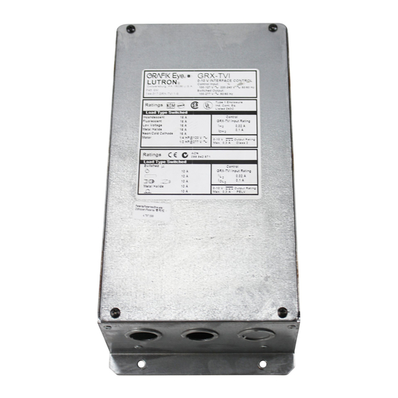
Product Specifi cations
Features.............................. Provides a IEC PELV/NECR Class 2
isolated 0-10 V- output signal that
conforms to EN60929 and IEC60929;
Accepts any phase control signal;
Accepts a constant-gate drive
fl uorescent signal (Control unit should
be confi gured for fl uorescent load type)
Input Power Rating............100-277 V~ 50/60 Hz
H2/L2 Terminal................... 20 mA
Input Rating
DH2/DL2 Terminal..............100 mA
Input Rating
0-10 V- Output Rating..... 10 μA-300 mA - Sinks current only
(maximum 150 ballasts/drivers)
Source/Load Type
Fluorescent:
Electronic Capacitive
Non-Dim
Other Manufacturer's 0-10 V-
Ballasts/drivers
(0-10 V- source only)
LED
Incandescent
Low-Voltage
Metal Halide
Neon/Cold Cathode
Motors
Terminals
Two 12 to 20 AWG (2.5 to 0.5 mm
per terminal.
Mounting
NEMA Type 1 enclosure, indoor use only.
Environmental 32 to 104 ˚F (0 to 40 ˚C).
Weight
4.25 lb (2 kg)
P/N 032443 Rev. A
230 V~ (CE)
100-277 V~ (Non-CE)
10 A
16 A
10 A
16 A
10 A
16 A
10 A
16 A
10 A
16 A
10 A
16 A
10 A
16 A
5 A @ 230 V~ CE
1/2 HP @ 100 - 120V~
1
1
⁄
HP @ 200 - 277 V~
2
2
) conductors
GRX-TVI Control Interface
100-277 V~ 50 / 60 Hz
System Wiring Layout Overview
0-10 V- Control Fluorescent Zone/Load 1
0-10 V- Ballast/driver
0-10 V- Control Fluorescent Zone/Load 1
0-10 V- Ballast/driver
Ballast/driver
GRX-
GRX-
TVI
TVI
Power from
Distribution
Control Unit / Dimmer
Panel
Note: When using a Control Unit, a GRX-TVI is required for each 0-10 V-
fl uorescent zone. (A 3-zone Control Unit with two fl uorescent zones and
one incandescent zone is shown as an example.)
Important Installation Information
• Install in accordance with all national and local electrical codes.
• Check for short-circuited loads during new installations before wiring
the GRX-TVI.
WARNING - Shock Hazard. To avoid the risk of electric
shock, locate and remove fuse or lock circuit breaker in the
OFF position before proceeding. Wiring with the power ON
could result in personal injury or death.
Note: Multiple power feeds could be provided. Ensure that all feeds
are off before wiring.
• Proper short circuit and overload protection must be provided at the
distribution panel. You can use up to a 20 A (16 A for CE) maximum
circuit breaker/MCB or equivalent (tripping curve C according to
IEC 898/EN60898 is recommended) with adequate short circuit
breaking capacity for your installation.
• Terminal blocks are rated for two 12 to 20 AWG (2.5 to 0.5 mm
wires per terminal.
• Strip 3/8 in (10 mm) of insulation from wires.
Note: 277 V~ operation on the control terminal was a design feature
added September 2013. To check whether your TVI has this feature,
please ensure the front label of the TVI shows the acceptable voltage
range as 100 - 277 V~ for the control input. Prior revisions of the unit
had (2) L2/H2 terminals (one for 120 V~ and one for 240 V~). The
current design of the unit accepts a universal voltage (100 - 277 V~),
so either of these terminals can be used for the control feed. They are
internally tied together.
1
Phase Control to 0-10 V-
Switch Fluorescent Zone/Load 2
Incandescent Zone/Load 3
LUTRON
LUTRON
Class 2/PELV Accessory Controls
3/8 in
(10 mm)
www.lutron.com
GRX-TVI
¨
0-10V INTERFACE CONTROL
Control Input:
100-120V,
220-240V 50/60Hz
COOPERSBURG, PA 18036 U.S.A.
Switches:
100-277VAC
2
)
Advertisement
Table of Contents

Related Manuals for Lutron Electronics Grafik Eye GRX-TVI


Summary of Contents for Lutron Electronics Grafik Eye GRX-TVI
- Page 1 GRX-TVI Control Interface GRX-TVI ¨ 0-10V INTERFACE CONTROL Control Input: 100-120V, 220-240V 50/60Hz P/N 032443 Rev. A COOPERSBURG, PA 18036 U.S.A. Switches: 100-277VAC Phase Control to 0-10 V- Installation and Operation Instructions 100-277 V~ 50 / 60 Hz Please Read Before Installing Occupant Copy Description System Wiring Layout Overview...
- Page 2 Mounting Wiring Find a suitable location for mounting. 1. Turn power off at fuse box or circuit breaker • Decide on the proper location for the GRX-TVI (NEMA Type 1 Warning - Shock Hazard. To avoid the risk of electric shock, locate and remove fuse or lock circuit breaker in the OFF enclosure, indoor use only).
- Page 3 Wiring Diagram A: 100-277 V~ GRX-TVI — 1 Distribution Panel - 1 Feed GRX-TVI L1/H1 is the Line/Hot feed that L2/H2 is internally shorted and powers the Switched Line/Hot is the Line/Hot feed that powers output to the load shown here as the internal circuitry of the 220- 100-...
-
Page 4: Operation
Some states do not allow the exclusion or limitation of incidental or consequential damages, so the above limitation or exclusion may not apply to you. Lutron, GRAFIK Eye, and Eco-10 are registered trademarks of Lutron Electronics Co., Inc. -
Page 5: Especificaciones Del Producto
Interfaz de control GRX-TVI GRX-TVI ¨ 0-10V INTERFACE CONTROL Control Input: 100-120V, 220-240V 50/60Hz P/N 032443 Rev. A COOPERSBURG, PA 18036 U.S.A. Switches: 100-277VAC Control de fase a 0-10 V- Instrucciones de instalación y operación 100-277 V~ 50 / 60 Hz Lea antes de instalar Copia del ocupante Descripción... -
Page 6: Montaje
Montaje Cableado Busque una ubicación adecuada para el montaje. 1. Desconecte la alimentación en el fusible o cortacircuitos. Advertencia - Peligro de descarga eléctrica. Para evitar el riesgo • Elija la ubicación adecuada para el GRX-TVI (NEMA, caja tipo 1, de descarga eléctrica, busque y retire el fusible o bloquee sólo para uso en interiores). - Page 7 Diagrama de cableado A: GRX-TVI de 100-277 V~ — 1 panel de distribución - 1 alimentación GRX-TVI L2/H2 está en corto circuito L1/H1 es la línea/vivo que alimenta interno y es la línea/vivo que la salida línea/vivo conmutada alimenta al circuito interno a la carga, que aquí...
-
Page 8: Operación
Algunos estados no permiten la exclusión o limitación de los daños incidentales o indirectos, de modo que la limitación o exclusión anterior puede no ser aplicable en su caso. Lutron, GRAFIK Eye, y Eco-10 son marcas registradas de Lutron Electronics Co., Inc. © 2013 Lutron Electronics Co., Inc. - Page 9 Interface de contrôle GRX-TVI GRX-TVI ¨ 0-10V INTERFACE CONTROL Control Input: 100-120V, 220-240V 50/60Hz P/N 032443 Rev. A COOPERSBURG, PA 18036 U.S.A. Switches: 100-277VAC Contrôle de phase de 0-10 V- Directives d’installation et de fonctionnement 100-277 V~ 50 / 60 Hz Veuillez lire avant l’installation Copie de l’utilisateur Description...
-
Page 10: Installation
Installation Câblage Trouvez un emplacement approprié pour le montage. 1. Couper l’alimentation au niveau de la boîte à fusibles ou du disjoncteur • Décidez sur l’emplacement idéal pour le GRX-TVI Attention - Danger d’électrocution. Pour éviter les chocs électriques, localiser et retirer le fusible ou verrouiller le disjoncteur en position (NEMA Boîtier Type 1, usage intérieur seulement). - Page 11 Schéma de câblage A : 100-277 V~ GRX-TVI — 1 Panneau de Distribution - 1 Entrée GRX-TVI Le L1/H1 est la Ligne/Phase qui alimente Le L2/H2 est court-circuité la sortie commutée Ligne/Phase à la intérieurement et est la charge démontrée ici comme étant Ligne/Phase qui alimente la la même tension que L2/H2.
- Page 12 Certaines juridictions ne permettent pas de limiter ou d’exclure les dommages indirects ou consécutifs, alors la limite ou exclusion ci- dessus peut ne pas s’appliquer dans votre cas. Lutron, GRAFIK Eye, et Eco-10 sont des marques de commerce enregistrées et déposées de Lutron Electronics Co., Inc. © 2013 Lutron Electronics Co., Inc.
-
Page 13: Especifi Cações Do Produto
Interface de controle GRX-TVI GRX-TVI ¨ 0-10V INTERFACE CONTROL Control Input: 100-120V, 220-240V 50/60Hz P/N 032443 Rev. A COOPERSBURG, PA 18036 U.S.A. Switches: 100-277VAC Controle de fase a 0-10 V- Instruções de instalação e operação 100-277 V~ 50 / 60 Hz Leia atentamente antes de instalar Cópia do ocupante Descrição... - Page 14 Cabeamento Montagem 1. Desligue a alimentação na caixa de fusíveis ou no disjuntor. Escolha um local adequado para a montagem. Atenção - risco de choques. Para evitar o risco de choques • Decida quanto à localização adequada do GRX-TVI (gabinete elétricos, localize e remova o fusível ou trave o disjuntor na NEMA tipo 1, para uso somente em ambientes fechados).
- Page 15 Diagrama de cabeamento A: GRX-TVI de 100-277 V~ — 1 painel de distribuição - 1 alimentação GRX-TVI L2/H2 está em curto L1/H1 é a alimentação de linha/ internamente e é a alimentação quente que alimenta a saída de de linha/quente que alimenta linha/quente comutada para a carga os circuitos internos do GRX- mostrada aqui como a mesma...
- Page 16 Alguns locais não permitem a exclusão ou limitação de danos acidentais ou consequentes, portanto, a limitação ou exclusão acima pode não se aplicar. Lutron, GRAFIK Eye, e Eco-10 são marcas comerciais registradas da Lutron Electronics Co., Inc. © 2013 Lutron Electronics Co., Inc.
- Page 17 GRX-TVI Steuerinterface GRX-TVI ¨ 0-10V INTERFACE CONTROL Control Input: 100-120V, 220-240V 50/60Hz Bestell-Nr. 032443 Rev. A COOPERSBURG, PA 18036 U.S.A. Switches: 100-277VAC Phasensteuerung von 0-10 V- Installations- und Betriebsanweisungen 100-277 V~ 50 / 60 Hz Bitte lesen Sie diese Anweisungen vor der Installation Anwenderexemplar Beschreibung Anordnung der Systemverkabelung...
-
Page 18: Montage
Montage Verkabelung 1. Schalten Sie die Sicherungsautomaten oder die Sicherungen aus. Suchen Sie eine geeignete Stelle für die Montage aus. Achtung - Stromschlaggefahr. Um Stromschlaggefahr zu • Legen Sie die richtige Stelle für das GRX-TVI fest (Schrank vermeiden, müssen Sie die Sicherung ausfi ndig machen und entfernen oder den Sicherungsautomaten in Aus-Position des Typs NEMA 1, nur in Innenräumen zu verwenden). - Page 19 Verkabelungsschema A: 100-277 V~ GRX-TVI — 1 Verteilerkaster - 1 Speisestrom GRX-TVI L2/H2 ist intern kurzgeschlossen L1/H1 ist die Einspeisung (Phase), und ist die Einspeisung (Phase), die den geschalteten Ausgang die die internen Schaltungen (Phase) zur Last wie hier gezeigt des GRX-TVI versorgt.
-
Page 20: Betrieb
Zeitdauer einer indirekten Garantie nicht begrenzt werden. In einigen Staaten ist es unzulässig, unmittelbare oder Folgeschäden auszuschließen oder zu begrenzen. Daher ist es möglich, dass obige Ausnahmen und Begrenzungen für Sie nicht gültig sind. Lutron, GRAFIK Eye und Eco-10 sind eingetragene Warenzeichen von Lutron Electronics Co., Inc. © 2013 Lutron Electronics Co., Inc. -
Page 21: Specifi Che Del Prodotto
Interfaccia di controllo GRX-TVI GRX-TVI ¨ 0-10V INTERFACE CONTROL Control Input: 100-120V, 220-240V 50/60Hz Cod. 032443 Rev. A COOPERSBURG, PA 18036 U.S.A. Switches: 100-277VAC Controllo di fase 0-10 V- Manuale d’uso e installazione 100-277 V~ 50 / 60 Hz Leggere attentamente prima di procedere all’installazione Copia per l’utilizzatore Descrizione Layout di cablaggio del sistema... -
Page 22: Installazione
Installazione Cablaggio Scelta della posizione adatta all’installazione. 1. Scollegare l’alimentazione dall’interruttore automatico o dal fusibile di alimentazione. • Decidere la posizione corretta per l’interfaccia GRX-TVI Avvertenza - Pericolo di folgorazione. Per evitare il rischio di (armadio NEMA tipo 1, solo per uso in ambienti interni). folgorazione, individuare e rimuovere il fusibile oppure bloccare •... - Page 23 Schema di cablaggio A: 100-277 V~ GRX-TVI — 1 quadro di distribuzione - 1 alimentazione GRX-TVI L2/H2 è cortocircuitata L1/H1 è la fase che alimenta l’uscita internamente ed è la fase di pilotaggio on/off del carico, che alimenta il circuito interno mostrata qui con la stessa tensione dell’interfaccia GRX-TVI.
-
Page 24: Funzionamento
Alcuni stati non prevedono l’esclusione o la limitazione dei danni diretti o indiretti, pertanto la limitazione di cui sopra potrebbe non essere applicabile a voi. Lutron, GRAFIK Eye, ed Eco-10 sono marchi registrati di Lutron Electronics Co., Inc. © 2013 Lutron Electronics Co., Inc. - Page 25 GRX-TVI besturingsinterface GRX-TVI ¨ 0-10V INTERFACE CONTROL Control Input: 100-120V, 220-240V 50/60Hz P/N 032443 rev. A COOPERSBURG, PA 18036 U.S.A. Switches: 100-277VAC Faseregeling voor 0-10 V- Voorschriften voor installatie en bediening 100-277 V~ 50 / 60 Hz Vóór installatie lezen Gebruikersexemplaar Beschrijving Overzicht schema systeembedrading...
- Page 26 Montage Bedrading Zoek een geschikte locatie voor montage. 1. Schakel de spanning uit via de zekeringenkast of de groepschakelaar. Waarschuwing – Gevaar voor elektrische schokken. Om het risico • Kies de juiste plaats voor de GRX-TVI (behuizing NEMA Type 1, van elektrische schokken te vermijden zoekt en verwijdert alleen voor binnen).
- Page 27 Bedradingschema A: 100-277 V~ GRX-TVI – 1 Verdeelbord - 1 voeding GRX-TVI L2/H2 zijn intern L1/H1 is de fasevoeding voor doorverbonden en de geschakelde faseuitgang voor vormen de fasevoeding de belasting, hier weergegeven die het interne circuit van als dezelfde spanning als L2/H2. de GRX-TVI van spanning 220- 100- 240 V~...
- Page 28 In sommige rechtsgebieden is de uitsluiting van of beperking van incidentele schade of gevolgschade niet toegestaan, zodat het mogelijk is dat de voorgaande beperking of uitsluiting niet op u van toepassing is. Lutron, GRAFIK Eye, en Eco-10 zijn gedeponeerde handelsmerken van Lutron Electronics Co., Inc. © 2013 Lutron Electronics Co., Inc.
- Page 29 GRX-TVI 控制接口 GRX-TVI ¨ 0-10V INTERFACE CONTROL Control Input: 100-120V, 220-240V 50/60Hz P/N 032443 Rev. A COOPERSBURG, PA 18036 U.S.A. Switches: 相位控制至 0-10 V- 100-277VAC 安装和操作说明 100-277 V~ 50 / 60 Hz 安装之前请参阅 用户手册 说明 系统接线布局概述 GRX-TVI 在一个封挡电柜中就能提供 0-10 V- 控制和镇流器/驱动 0-10 V- 控制荧光灯光区/负载...
- Page 30 安装 接线 找到适合的安装位置。 1.切断保险丝盒或断路器上的电源。 • 决定 GRX-TVI 的正确位置(NEMA 1 型封挡电柜,仅限室内 警告 – 触电危险。为防止触电,在继续操作之前要找到并拆 使用)。 下保险丝或将断路器锁在断开位置。在通电的情况下进行接线 可导致人员受伤或死亡。 • GRX-TVI 安装场所的环境温度必须在 0 至 40 °C(32 至 104 °F) 范围内。 • 在墙上垂直安装封挡电柜(不提供螺丝)。 • 所采用的安装方法必须能够支持安装期间的重量和所施加的力。 • 运行时机内的继电器会产生卡卡声。请在可以容许这种噪声的地方 进行安装。 注:可能提供了多路电源馈线。接线前,确保所有馈线都已断开。 2.使用提供的接线端子按照相应的接线图(参见下页)来进行接线控 安装图 制。图中的点代表接线端子。 Four Screws 四个安装孔...
- Page 31 接线图 A: 100-277 V~ GRX-TVI — 1 个配电柜 – 1 个馈线 GRX-TVI L1/H1是火线馈线,用于向开关火线 供电,输出至负载,如此处所示, L2/H2 内部短接,是向 GRX-TVI 与 L2/H2 电压相同。 内部电路供电的火线馈线。 使用 100-277 V~ 范围内的电 220- 100- 240 V~ 120 V~ 压。参考第 1 页底部的注。 注:0-10 V- 控制信号线 —不要与线电压相连。LutronR 对于由于 接线错误造成的损害不承担任何责任。 0-10 V- 镇流器/驱动器...
- Page 32 Lutron 有权根据自己的选择决定修理或更换任何自购买后一年内出现材料或工艺缺陷的产品。凡属于质量保证范围内的维修产品,请将产品退回给经销商或以邮资预付的方式将其寄 到 Lutron 在美国的地址(7200 Suter Rd., Coopersburg, PA 18036-1299)。 本品质保证取代所有其它明示的保证,而且其适销性默示保证仅限于购买后一年时间内。本品质保证不包括安装、拆除或重新安装的费用,也不包括由于使用不当、滥用、修理不当 或修理错误所引起的损坏或由于接线或安装不正确所导致的损坏。附带或间接损失不在本品质保证范围内。Lutron 对任何直接或间接与产品的制造、销售、安装、运送或使用有关的 索赔责任,仅承担不超过产品的购买价格。 本质量保证赋予您特定的法律权利,您同时也可享受各州规定的其它权利。有些州不允许限制默示保证的时间长短,那么上述限制可能对您不适用。有些州不允许对附带损失或间接 损失进行排除或限制,那么上述限制或排除可能对您不适用。 Lutron GRAFIK Eye Eco-10 是 Lutron 电子公司的注册商标。 © 2013 Lutron Electronics Co., Inc. Lutron Electronics Co., Inc. 7200 Suter Road Coopersburg, PA 18036-1299 09/2013...
Need help?
Do you have a question about the Grafik Eye GRX-TVI and is the answer not in the manual?
Questions and answers