
Subscribe to Our Youtube Channel
Related Manuals for MasterCraft 062-3593-2


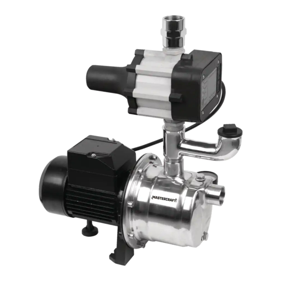
Summary of Contents for MasterCraft 062-3593-2
- Page 1 SHALLOW WELL JET PUMP WITH ELECTRONIC PRESSURE CONTROL Model No. 062-3593-2 IMPORTANT: INSTRUCTION Please read this manual carefully before running this MANUAL jet pump and save it for reference.
- Page 2 headline bars headline bars continuation tabs notes continuation tabs warnings notes warnings...
- Page 3 TABLE OF CONTENTS Quick Start Guide Technical Specifications Safety Guidelines Important Information Key Parts Diagram Assembly Instructions Operating Instructions Troubleshooting Warranty NOTE: If any parts are missing or damaged, or if you have any questions, please call our toll-free helpline at 1-800-689-9928. SAVE THESE INSTRUCTIONS This manual contains important safety and operating instructions.
- Page 4 062-3593-2 | contact us 1-800-689-9928 SHALLOW WELL INSTALLATION Connect the suction pipe to the pump inlet. Check valve continuation tabs continuation tabs Max. 25' (7.6 m) Pipe Foot valve notes notes Prime the pump.
- Page 5 TYPICAL HOUSEHOLD BOOSTER INSTALLATION Connect all the pipe lines as the To household diagram shows, then turn on the faucet (pump discharge) and all the ball valves and allow water flow. When a steady stream of water Grounded, GFCI protected flows out of the faucet, close the faucet 115 V outlet and the ball valve in the main water...
- Page 6 062-3593-2 | contact us 1-800-689-9928 TECHNICAL SPECIFICATIONS Temperature 32 to 77ºF (0 to 25ºC) Impeller Plastic Solids handling 0” (0 mm) spherical Discharge /suction size 1” (2.5 cm) national pipe thread (NPT) continuation tabs...
- Page 7 PERFORMANCE CHART Lift height 0’ 5’ 10’ 15’ 20’ 25’ (0 m) (1.5 m) (3 m) (4.6 m) (6 m) (7.6 m) Gallons per hour Litres per hour (2271) (2135) (1999) (1817) (1544) (1226) All performances shown at 30 PSI discharge pressure. DIMENSIONS 17 1/16"...
- Page 8 • Mastercraft Canada is not responsible for losses, injury, or death resulting from a failure to observe these safety precautions, or the misuse or abuse of pumps or equipment..
- Page 9 UNPACKING • Upon receiving the pump, it should be inspected for damage or shortages. If damage has occurred, file a claim immediately with the carrier that delivered the pump. If the manual is removed from the packaging, do not lose or misplace. STORAGE •...
- Page 10 062-3593-2 | contact us 1-800-689-9928 SAFETY GUIDELINES WIRE SIZE • Consult a qualified electrician for proper wire size. PRE-OPERATION: CHECK VOLTAGE AND PHASE • Before operating pump, check to make sure that the voltage and phase information...
- Page 11 GENERAL USE • Pump only clean water with your pump. To avoid clogging the pump and damaging the shaft seal, do not pump water containing solids, foreign material, sand, silt, or abrasives. • If you are boosting the pressure from a well pump, be sure that the system check valves are tight.
- Page 12 062-3593-2 | contact us 1-800-689-9928 PARTS LIST Description Qty. Description Qty. Pressure gauge Connector Pump body Electronic control Connection wire continuation tabs Power cord Motor Plug Priming elbow notes warnings...
- Page 13 MATERIALS REQUIRED (NOT INCLUDED) Ball valve Check valve Discharge tee Pipe Union Threaded adaptor Elbow TOOLS REQUIRED PVC glue Thread tape Flathead screwdriver Pipe wrench Tape measure Hacksaw DETERMINE THE DEPTH OF YOUR WELL Tie a small but heavy weight such as a fishing weight to the end of a piece of cotton string. Lower the weight into the well until it reaches the bottom of the well.
- Page 14 062-3593-2 | contact us 1-800-689-9928 INSTALLATION 1. Decide where the best place is to install the pump. Think about these things: • It must be near the main water supply line. • The pump must be accessible.
- Page 15 10. With all pipe and fittings installed and sealed, To household turn on all the ball valves and the main water (pump discharge) supply slowly to pressurize the system and check for leaks. If any leaks appear, turn the Grounded, GFCI main valve off, open a faucet to relieve the protected pressure, and repair the leak.
- Page 16 062-3593-2 | contact us 1-800-689-9928 AUTOMATIC PRESSURE CONTROLLER The automatic pressure controller mounts on the pump. It protects against: • Run-dry operation. • Frequent starts caused by small water losses in the system. • Pressure drop.
- Page 17 NORMAL OPERATION OF THE PUMP Fill the pump with water before starting it. Make sure that the pump has been properly installed and primed, and that the suction pipe is unobstructed and open. Plug in the pump. The ‘Power on’ and ‘Pump on’ lights will come on indicating, respectively, that voltage is present and that the pump is ready to operate.
- Page 18 062-3593-2 | contact us 1-800-689-9928 TROUBLESHOOTING Problem Possible Causes Solutions Motor will not run. Fuse is blown or circuit breaker DISCONNECT POWER. Replace fuse or reset tripped. circuit breaker. Power cord not plugged in. Plug into 115 V grounded outlet.
- Page 19 This Mastercraft product is guaranteed for a period of three (3) years from the date of original retail purchase, against defects in materials and workmanship. Subject to the conditions and limitations described below, this product, if returned to us with proof of purchase within the stated warranty period and if covered under this warranty, will be repaired or replaced (with the same model, or one of equal value or specification), at our option.
Need help?
Do you have a question about the 062-3593-2 and is the answer not in the manual?
Questions and answers