
Related Manuals for MasterCraft 062-3425-4


Summary of Contents for MasterCraft 062-3425-4
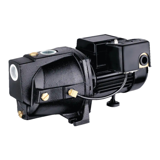
- Page 1 062-3425-4 Cast Iron SHALLOW WELL JET PUMP IMPORTANT: INSTRUCTION Please read this manual carefully before running MANUAL this pump and save it for reference.
- Page 2 062-3425-4 | contact us 1-800-689-9928...
-
Page 3: Table Of Contents
TABLE OF CONTENTS Technical Specifications Safety Installation Preparation Installation Instructions Key Parts Diagram Troubleshooting Warranty NOTE: If any parts are missing or damaged, or if you have any questions, please call our toll-free helpline at 1-800-689-9928. SAVE THESE INSTRUCTIONS This manual contains important safety and operating instructions. Read all instructions and follow them with use of this product. -
Page 4: Technical Specifications
062-3425-4 | contact us 1-800-689-9928 TECHNICAL SPECIFICATIONS Model Number 062-3425-4 Voltage 115 / 230 V ~ 60 Hz Horsepower 1/2 HP Amps 3.3/6.6 A Max. Head 108' (32.9 m) Max. Flow Discharge Size 1" (2.5 cm) PERFORMANCE 5' (1.5 m) 10' (3 m) 15' (4.5 m) -
Page 5: Safety
SAFETY WARNING • This pump is meant to be used where the vertical lift of water is less than 25' (7.6 m). If the well is deeper than that, you need to purchase a deep well convertible jet pump. • Do not pump flammable or explosive liquids such as oil, gasoline, kerosene, ethanol, etc. - Page 6 062-3425-4 | contact us 1-800-689-9928 ADDITIONAL SAFETY PRECAUTIONS 1. Know the pump applications, limitations, and potential hazards. 2. Make certain the electrical power source is adequate for the requirements of the pump. 3. ALWAYS disconnect the power to the pump before servicing.
-
Page 7: Installation Preparation
INSTALLATION PREPARATION PREPARATION Before beginning assembly of product, make sure all parts are present. If any part is missing or damaged, do not attempt to assemble the product. Contact customer service for replacement parts. Estimated Assembly Time (new installation): 30 – 60 minutes Tools Required for Assembly (not included): Wrench, Pliers, Cross-head Screwdriver, Thread Tape, PVC Purple Primer, and PVC Cement Accessories Required for Assembly (not included):... - Page 8 062-3425-4 | contact us 1-800-689-9928 LOCATION OF THE PUMP Decide on the area for the pump installation. Select a pump location with adequate space for future pump maintenance. It can be located in the basement or utility room of the house, at the well, or between the house and the well. If installed outside of the house, it should be protected by a pump house with auxiliary heat to prevent possible freezing.
-
Page 9: Installation Instructions
Wrap thread tape (not included) around threads of a 1 1/4" (3.2 cm) male PVC adaptor (not included). Thread adaptor into a 1 1/4" (3.2 cm) foot valve. Hand tighten, then tighten 1/2 turn with a pipe wrench. Subtract 5' (1.5 m) from the depth of the well. - Page 10 062-3425-4 | contact us 1-800-689-9928 Using PVC purple primer and PVC cement, attach a 1 1/4" (3.2 cm) PVC elbow (not included) onto the rigid PVC pipe extending from the well seal. Wrap thread tape around the threads of a male PVC adaptor (not included).
- Page 11 Wrap all threads with thread tape. In order for the pump (A) and the pressure tank (not included) to operate properly, the pressure tank needs to be drained of all water BEFORE INSTALLING IT TO THE PUMP. Thread a 10" (25.4 cm) tank tee (not included) or another necessary size tee into the pressure tank.
- Page 12 062-3425-4 | contact us 1-800-689-9928 To prime, remove both: a. The plug from the top of the discharge tee (water will be filled in here); and b. The priming plug in front of the discharge tee (this is to allow air to vent out while priming).
- Page 13 PRESSURE SWITCH INSTALLATION INSTRUCTIONS To complete the installation, you must connect the power source to the pressure switch. A 30/50 PSI pressure switch has been installed on the pump. The pressure switch allows for automatic operation; the pump starts when pressure drops to the “cut-in”...
-
Page 14: Key Parts Diagram
062-3425-4 | contact us 1-800-689-9928 KEY PARTS DIAGRAM PARTS LIST Description Description Pump body Motor Interval channel Mechanical seal Drain cover O-ring Impeller... -
Page 15: Troubleshooting
TROUBLESHOOTING Problem Possible Cause Corrective Action Pump does not 1. Power off. 1. Turn power on or call power company. start or run. 2. Blown fuse or tripped breaker. 2. Replace fuse or reset circuit breaker 3. Faulty pressure switch. 3. -
Page 16: Warranty
PLEASE DO NOT ATTEMPT TO OPEN OR REPAIR THE PUMP YOURSELF. DOING SO COULD VOID THE WARRANTY AND CAUSE DAMAGE OR PERSONAL INJURY. This Mastercraft product carries a three (3) year LIMITED warranty against defects in workmanship and materials. This product is not guaranteed against wear or breakage due to misuse and/or abuse.
Need help?
Do you have a question about the 062-3425-4 and is the answer not in the manual?
Questions and answers