
Related Manuals for Steel City 20-400


Summary of Contents for Steel City 20-400
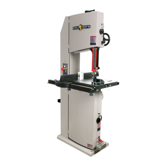
- Page 1 15” BAND SAW 20-400 For technical support, provide the following model and serial numbers: Model No: ______________________ Serial No: ______________________...
- Page 2 The manufacturer warrants its machines to be free from defects in workmanship and materials for a period of 2 years from the date of the original purchase for Steel City shop machines or for a period of 1 year for Titanium production machines;...
-
Page 3: Table Of Contents
The drawings, illustrations, photographs, and specifications in this user manual represent your machine at time of print. However, changes may be made to your machine or this manual at any time with no obligation to Steel City. ProduCT sPeCiFiCATions Motor... -
Page 4: Safety
sAFeTY This manual is not totally comprehensive. it does not and can not convey every possible safety and operational problem which may arise while using this machine. The manual will cover many of the basic and specific safety procedures needed in an industrial environment. wArning All federal and state laws and any regulations having jurisdiction covering the safety requirements for use of this... - Page 5 22. do noT operate any machine or tool if under the 4. Prevent electrical shock. Follow all electrical and safety codes, including the National Electrical Code (NEC) and influence of drugs, alcohol, or medication. the Occupational Safety and Health Regulations 23.
- Page 6 ProduCT sAFeTY 1. Replace any blade that, when rotating, has a more 3. Do not get your fingers closer than 2 " to the blade. Use pronounced forward-to-back motion than average. a pusher or pull the wood from the back of the blade. Generally, welding is involved and these blades break quickly.
-
Page 7: Electrical And Grounding Instructions
eLeCTriCAL And grounding insTruCTions wArning iMProPer eLeCTriCAL ConneCTion equipment-grounding conductor can result in risk of electric To reduce the risk of electric shock, follow all shock. The conductor with the green insulation (with or electrical and safety codes, including the without yellow stripes) is the equipment-grounding National Electric Code (NEC) and the conductor. -
Page 8: Unpacking And Inventory
unPACKing & inVenTorY degreAsing wArning In order to prevent any corrosion during transport, an antirust has been applied. Above all, greasy surfaces should be wiped clean and cleaned with a clean cloth and This machine is heavy, more degreaser. Refer to the safety instructions for this type of than one person is required to product. -
Page 9: Assembly
AsseMBLY ◊ TABLe wArning 1. Remove the bolt located on the rear compass of the Make sure the switch is in the off position and machine frame. the machine is unplugged. Bolt to be removed ◊ desAsseMBLing THe BLAde 1. Unlock each of the protective covers and loosen the clamping handles. - Page 10 ◊ PArALLeL guide 5. Align the compass’s passage hole from step 1 with the passage hole in the bracket and insert the bolt removed 1. Using two hex bolts, two lockwashers and two washers, in step 1. assemble the two L-brackets at the front of the table. Hand tighten for the moment.
- Page 11 ◊ sTorAge The bottom of the guide should not rub on the cast iron table. Three points consisting of the two ball bearings Unscrew the 4 screws on the frame and attach the hook and the plastic cylinder must be the only points of and the box.
-
Page 12: Adjustments
AdjusTMenTs ◊ BLAde Tension wArning Make sure the switch is in the off position and 1. Lower the tension lever of the blade and evaluate the the machine is unplugged tension exerted found on the scale located behind the high wheel ◊... - Page 13 wArning Rear bearing Rear bearing lock Make sure the switch is in the off position and the machine is unplugged. Torwards the interior of the fram Torwards the exterior of the frame 3. To lock the adjustment, hold the handle with one hand and tighten the locknut firmly with the other hand.
- Page 14 ◊ TABLe squAring ◊ FrequenCY oF roTATion A hexagon bolt fitted with a counter nut is the stop for quickly adjusting the table to 90 ° relative to the blade. 2 rotation frequencies are possible. The choice of a frequency is defined by the type of material. Material harder, thicker = reduced rotation frequency.
- Page 15 ◊ CAPACiTY oF sAwing HeigHT To adjust the indicator on the scale, unscrew 1. Unlock the handle. the screw. Move the 2. Turn the handle to adjust the height of the guide device indicator to its position and lock the handle. and tighten the screw.
-
Page 16: Maintenance
MAinTenAnCe wArning Make sure the switch is in the off position and the machine is unplugged. dusT CAPTure wArning using this machine without dust collection equipment can cause premature wear of the ma- chine, but also health problems for the user and others working in the workshop. -
Page 17: Part Lists
PArT LisTs Page 17... - Page 18 Page 18...
- Page 19 PArT LisTs Page 19...
- Page 20 Page 20...
- Page 21 Page 21...
- Page 22 noTes Page 22...
Need help?
Do you have a question about the 20-400 and is the answer not in the manual?
Questions and answers