
Subscribe to Our Youtube Channel
Related Manuals for Steel City 35920


Summary of Contents for Steel City 35920
-
Page 1: Model Number
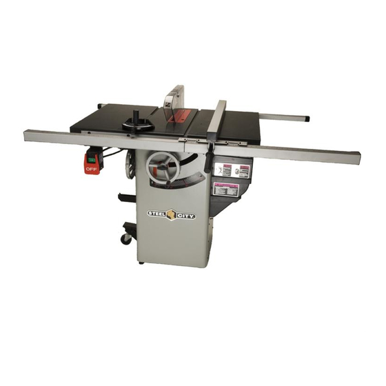
10" GRANITE CABINET SAW Model 35920 Shown Model Number 35929 35920 STEEL CITY TOOL WORKS VER. 12.08 Manual Part No. SC75009... -
Page 2: Table Of Contents
The drawings, illustrations, photographs, and specifications in this user manual represent your machine at time of print. However, changes may be made to your machine or this manual at any time with no obligation to Steel City Tool Works. - Page 3 Model No. 35929 Model No. 35920 Induction Motor Induction 1.75 1.75 Amps 15 / 7.5 15 / 7.5 120 / 240 Volts 120 / 240 Hertz 3450 3450 Blade Tilt Left Left Poly-V Belt Blade Drive Poly-V Belt 10-in Blade Diameter...
-
Page 4: Section 3 Accessories And Attachments
ACCESSORIES AND ATTACHMENTS There are a variety of accessories available for your Steel City Product. For more information on any accessories associated with this and other machines, please contact your nearest Steel City distributor, or visit our website at : www.steelcitytoolworks.com. - Page 5 A) Miter Gauge B) Blade Guard Assembly with riving knife C) Motor Cover D) Bevel Scale E) Height Adjustment Handwheel F) Bevel Adjustment Handwheel G) Fence Hooks (2) H) On/Off Switch I ) Mobile Base Caster Assembly...
-
Page 6: Section 6 General Safety
GENERAL SAFETY WARNING WARNING TO AVOID serious injury and damage to the machine, read and follow all Safety and Operating Instructions before assembling and operating this machine. This manual is not totally comprehensive. It does not Exposure to the dust created by power sanding, saw- and can not convey every possible safety and opera- ing, grinding, drilling and other construction activities tional problem which may arise while using this... - Page 7 11. DO NOT FORCE the machine to perform an opera- WARNING tion for which it was not designed. It will do a safer and higher quality job by only performing operations for which the machine was intended. 12. DO NOT stand on a machine. Serious injury could result if it tips over or you accidentally contact any 3.
-
Page 8: Section 7 Product Safety
9. DO NOT handle the plug or table saw with wet hands. 10. USE accessories only recommended by Steel City. 11. DO NOT pull the table saw by the power cord. 4. TO REDUCE the risk of electrical shock. DO NEVER allow the power cord to come in contact NOT use this machine outdoors. - Page 9 Voltage from 120 Volt to 240 Volt. This manual is written for two specific models, Model No 35929,35920. Please follow the specific requirements for your model saw. The switch provided with your saw is a dual voltage capable switch, meaning it is designed to function at either 120 or 240 volts.
- Page 10 In the event of a malfunction or breakdown, GROUND- provides the path of least resistance for electric The smaller the gauge-number, the larger the diameter current and reduces the risk of electric shock. The plug of the extension cord is. If in doubt of the proper size of MUST be plugged into a matching electrical receptacle an extension cord, use a shorter and thicker cord.
-
Page 11: Section 11 Assembly
For missing parts, motors and moving parts. Lay out all parts on a clean contact Steel City at 1-877-SC4-TOOL. work surface. A) Blade Guard and Splitter Assembly B) Mobile Base Caster Assembly... - Page 12 1/4-20x1/2" ROUND HD TAP SCREW (4) for dust chute M4x8mm ROUND HD TAP SCREW (2) WRENCH HOOK 1/4-20x3/8"ROUND HD TAP SCREW (4) FENCE BRACKET (2) GRANITE EXTENSION WING Support Bar(2) M8x20mm HEX SOC SET SCREW (4) 5/16-18 HEX NUT (3) M8 LOCK WASHER (3) M8 FLAT WASHER (3) 5/16-18x2"...
- Page 13 HANDWHEEL ASSEMBLY • The table saw is a heavy machine; two people may be required for certain assembly operations. • DO NOT assemble the table saw until you are sure the tool is unplugged. • DO NOT assemble the table saw until you are sure the power switch is in the "OFF"...
-
Page 14: Section 12 Adjustments
WRENCH AND FENCE HOOK Fig. 5 ASSEMBLY Fig. 4 Fig. 6 1. Assemble both of the fence hooks (A) to the left side of the cabinet (B) using four 1/4-20x3/8" (4) round head screws. 2. Assemble wrench hook (C) to the left side of cabinet (B) using (2) 1/4-20x3/8”... - Page 15 Fig.9 GRANITE EXTENSION WING ASSEMBLY CAUTION: The granite extension wing is heavy; two people are required for assemble. 1. Install 2 T supporting bars (A) into the T-slot under main table. SEE FIG 7. Make sure the support bar is installed all the way into the slot, under the main table.
- Page 16 Fig. 13 RIVING KNIFE COMPONENTS ASSEMBLY Note: Remove the table insert retaining bolt used to secure the table insert (A) to the saw table. SEE FIG 12 Fig. 12 Fig. 14 INSTALLING AND REMOVING THE RIVING KNIFE 1. Line up the riving knife in the proper direction to the mounting bracket (B).
- Page 17 5. Replace the table insert and tighten the table insert 1. Remove the hex nut (K) and outer flange (J) from the retaining bolt removed instep 1. blade arbor (I). Note: The arbor has a right hand thread; to loosen the hex nut turn it counterclockwise. 6.
- Page 18 To tilt the blade bevel to 45-degrees, loosen the hand- RAISING AND LOWERING THE BLADE wheel lock knob (counterclockwise) and turn the hand- wheel clockwise. When the saw blade is at 45-degrees it Fig. 20 will come into contact with the adjustable positive stop which will cause the blade to stop.
-
Page 19: Section 13 Operations
Fig. 22 1. Raise the saw blade to its highest point. 2. Place a combination square (A) on the saw table with one edge (B) of the square against the left miter slot (C). SEE FIG 23. 3. Adjust the square so the rule (D) just touches the saw blade. - Page 20 BEVEL ARROW ADJUSTMENT Fig. 25 1. Make certain that the blade is at 90-degrees to the Table surface with a combination square. Fig. 27 1. To align the blade parallel to the miter slot, first loosen two hex head screws (A) under the left side of the table saw.
- Page 21 1. The table insert (A) must always be level with the saw 2. Remove blade guard, splitter and riving knife. table (B). To adjust the table insert, loosen and remove NOTE: can not insert the blade guard after the table table insert retaining bolt (C).
- Page 22 1. Make sure the switch is and disconnect power "OFF" ADJUSTING POSITIVE STOPS cord from power source. Fig. 32 2. Open motor cover and verify on the motor tag that motor is dual voltage. 3. If motor tag states that it is dual voltage remove junction box cover (A) on motor (B).
- Page 29 FENCE INSTALL TO INSTAll RIP FENCE- FOR 35920 ONLY 1. Place the rear clamp (A) under the rear rail of the saw table and pull slightly toward the front of the unit 2. Lower the front end of the rip fence (B) onto the guide surface on top of the front rail.
-
Page 30: Section 15 Troubleshooting Guide
TROUBLESHOOTING GUIDE This section covers the most common processing problems encountered in sawing and what to do about them. Do not make any adjustments until the table saw is unplugged and moving parts have come to a complete stop. PROBLEM LIKELY CAUSE(S) SOLUTION 1.Overload tripped. - Page 32 PART PART DESCRIPTION DESCRIPTION SC10136 BLADE GUARD ASSY Or91775 M4x15mm PAN HD SCREW OR91785 PUSH NUT OR91082 CURSOR OR91781 BLADE GUARD PIN OR91081 PLUNGER BLOCK SC10137 "SEE THRU" BLADE GUARD OR91080 PLUNGER OR91574 WARNING LABEL OR90143 M4 FLAT WASHER OR91575 WARNING LABEL PICTORAL OR91076 MITER GAGE BODY...
- Page 34 PART PART DESCRIPTION DESCRIPTION 5/8-18 JAM NUT OR91766 SC84005 SPRING PIN 4x20mm 242A ARBOR PULLEY OR91020 SC10194 WORM GEAR 242B 5x5x15mm KEY OR91824 SC10195 ELEVATING SHAFT ARBOR SPACER 1.75HP 203A OR91732 SPRING PIN 4x22mm OR91795 M5x12mm PAN HD SCR OR92137 HEX NUT SC10192 <60042Z>...
- Page 35 PART PART DESCRIPTION DESCRIPTION FENCE ASSY ---FOR 35920 ONLY OR94575 SC10290 OR94576 SC10279 OR90306 M6X12mm PAN HD SCR SC10280 301A OR91739 SC10281 301B 5/16-18*5/8 HEX HD SCR OR94577 SC80112 OR94578 OR90311 OR94579 FENCE LOCK KNOB ASSEMBLY OR90248 OR91736 SC10282 M6X10mm HEX HD SCR SC10288 SCALE, LEFT 20"...
- Page 36 401D(4) 401C 401A 420(4) 401B 403(3) 427A 429 (4) 428 (2) 429B(2) 429A(2) 405(4) 402B(4) 402A(4) 405A(4) 423(3) 426(4) 409(6) 434(2) 421(2) 433(2) 439(2) 408(3) 438(2) 440(2) 441(2) 442(2)
- Page 37 PART PART DESCRIPTION DESCRIPTION SC10291 CABINET ASS Y WELDMENT OR72922 REAR WHEEL BRACKET 401A SC76025 OR91503 5/16-18 LOCK NUT SPECIAL LABEL 401B OR70160 M8x20mm CARRIAGE BOLT OR94775 BEVEL SCALE 401C SC10218 M8 HEX NUT OR94771 CABINET ACCESS DOOR 401D SC80412 M8x50HEX HD BOLT OR91497 M4x8 ROUND HD TAP SCR...
Need help?
Do you have a question about the 35920 and is the answer not in the manual?
Questions and answers