
Related Manuals for Steel City 35620


Summary of Contents for Steel City 35620
-
Page 1: User Manual
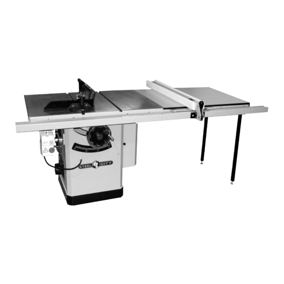
User Manual Read and understand this manual before using machine. 10” TABLE SAW Shown with optional Industrial Fence and Extension Table Model Numbers 35620, 35631 ® STEEL CITY TOOL WORKS Manual Part No. OR70785 VER. 3.07... -
Page 3: Table Of Contents
The drawings, illustrations, photographs, and specifications in this user manual represent your machine at time of print. However, changes may be made to your machine or this manual at any time with no obligation to Steel City Tool Works. -
Page 4: Warranty
STEEL CITY TOOL WORKS 5 YEAR LIMITED WARRANTY Steel City Tool Works, LLC (“SCTW”) warrants all “STEEL CITY TOOL WORKS” machinery to be free of defects in workmanship and materials for a period of 5 years from the date of the original retail purchase by the original owner. - Page 5 City:______________________________________________ ___ Vacuum Veneer Press ___ Wide Belt Sander Other____________________________________________ How did you first learn of Steel City Tool Works? ___ Advertisement ___ Mail Order Catalog 11. Which benchtop tools do you own? Check all that apply. ___ Web Site...
- Page 6 FOLD ON DOTTED LINE PLACE STAMP HERE Steel City Tool Works P.O. Box 10529 Murfreesboro, TN 37129 FOLD ON DOTTED LINE...
-
Page 7: Product Specifications
3450 ACCESSORIES AND ATTACHMENTS There are a variety of accessories available for your Steel City Product. For more information on any accessories associated with this and other machines, please contact your nearest Steel City distributor, or visit our website at: www.steelcitytoolworks.com. -
Page 8: Definition Of Terms
DEFINITION OF TERMS Anti-Kickback Fingers – A safety device attached to Heeling – The misalignment of the blade to the miter the blade guard and splitter assembly designed to mini- slots; when the blade is not parallel to the miter slots. mize the chance of a workpiece being thrown back dur- ing a cutting operation. -
Page 9: Feature Identification
FEATURE IDENTIFICATION A. Miter Gauge Assembly B. Blade Guard Assembly C. Blade Height Adjustment Handwheel D. Blade Height Lock Knob E. Bevel Adjustment Handwheel F. Bevel Lock Knob G. Switch H. Motor Cover Dust Port (shown with optional industrial fence and extension table) -
Page 10: General Safety
GENERAL SAFETY WARNING WARNING TO AVOID serious injury and damage to the machine, read and follow all Safety and Operating Instructions before assembling and operating this machine. This manual is not totally comprehensive. It does not Exposure to the dust created by power sanding, saw- and can not convey every possible safety and opera- ing, grinding, drilling and other construction activities tional problem which may arise while using this... - Page 11 11. DO NOT FORCE the machine to perform an opera- WARNING tion for which it was not designed. It will do a safer and higher quality job by only performing operations for which the machine was intended. 12. DO NOT stand on a machine. Serious injury could result if it tips over or you accidentally contact any 3.
-
Page 12: Product Safety
9. DO NOT handle the plug or table saw with wet hands. 10. USE accessories only recommended by Steel City. 11. DO NOT pull the table saw by the power cord. 4. TO REDUCE the risk of electrical shock. DO NEVER allow the power cord to come in contact NOT use this machine outdoors. -
Page 13: Electrical Requirements
14. DO NOT use the table saw as a toy. DO NOT use 22. DO NOT use the rip fence as a guide when cross- near or around children. cutting 15. ENSURE that the machine sits firmly on the floor 23. -
Page 14: Extension Cords
GROUNDING INSTRUCTIONS The motor supplied with your machine is a 230 volt, WARNING 60 hertz, single phase motor. Never connect the green or ground wire to a live terminal. A machine with a 230 volt plug should only be connect- ed to an outlet having the same configuration as the plug. -
Page 15: Unpacking & Inventory
“ON” after all the parts have been work surface. obtained and installed correctly. For missing parts, contact Steel City at 1-877-SC4-TOOL. Remove any protective materials and coatings from all of the parts and the table saw. The protective coat- ingscontact Steel City at 1-877-SC4-TOOL. - Page 16 Blade Guard Assembly J. Left and Right Cast Iron Wings K. Motor Cover...
-
Page 17: Assembly
ASSEMBLY Fig. 1 WARNING MAKE CERTAIN THAT THE SAW IS DISCONNECT- ED FROM THE POWER SOURCE. INSTALLATION AND LEVELING Final location for the saw must be level, dry, well light- ed, and have enough room to allow movement around the saw with long pieces of wood stock. Level the saw front to back and side to side, using a carpenter’s level placed on the table. -
Page 18: Handwheel Assembly
HANDWHEEL ASSEMBLY Fig. 5 Fig. 3 1. Line up the key on the shaft with the keyway in the INSTALLING BLADE handwheel (A), and slide the handwheel onto the shaft. SEE FIG. 3. WARNING 2. Tighten the set screw on the handwheel hub securely to hold in place. -
Page 19: Adjustments
ADJUSTMENTS ALIGNING BLADE GUARD TABLE INSERT ADJUSTMENT AND SPLITTER WARNING WARNING MAKE CERTAIN THAT THE SAW IS DISCONNECT- ED FROM THE POWER SOURCE. MAKE CERTAIN THAT THE SAW IS DISCONNECT- Fig. 8 ED FROM THE POWER SOURCE. Fig. 7 1. Lower blade completely. 2. -
Page 20: Blade Alignment
BLADE RAISING AND BLADE ALIGNMENT TILTING MECHANISM Blade alignment with the table is adjusted at the factory. After a period of use, or after moving the saw to an- Fig. 10 other location, the blade may no longer be aligned with the table. -
Page 21: Positive Stops
Fig. 13 1. Raise the saw blade to its maximum height using the blade height handwheel. 2. Set the blade at 90 degrees to the table by turning the blade tilting handwheel clockwise as far as it will go. 3. Place a square on the table and check to see that the blade is at a 90°... - Page 22 Fig. 17 5. Tighten the lock nut (A). 6. Set the blade at 45 degrees to the table by turning the blade tilting handwheel counterclockwise as far as it will go. Place a square on the table. SEE FIG. 16. Fig.
-
Page 23: Operations
OPERATIONS PRE-RUN CHECK WARNING WARNING MAKE CERTAIN THAT THE SAW IS DISCONNECT- ED FROM THE POWER SOURCE. MAKE CERTAIN THAT THE SAW IS DISCONNECT- ED FROM THE POWER SOURCE. Before you begin to use your Table Saw, you should give it a thorough inspection, making sure you ask WARNING yourself the following questions: 1. -
Page 24: Blade Selection
BLADE SELECTION 3. Combination Blade: Used for cutting with and across the grain. A compromise between a rip blade Choosing the correct blade for the job is essential for and a cross-cut blade, a 10” combination blade will the safe and efficient use of your table saw. Ignoring typically have between 40-50 teeth. - Page 25 CROSSCUTTING RIPPING Crosscutting means cutting across the grain of the Ripping means to cut with the grain of the wood. In wood. In wood products without grain (i.e. MDF, other materials such as MDF or plywood, ripping simply means to cut lengthwise. To rip a board: particleboard), crosscutting simply means cutting across the width of the stock.
-
Page 26: Dado Operations
Do not stand directly behind the workpiece when WARNING ripping. SEE FIG. 24. Fig. 24 Dado operations present very real hazards requiring proper procedures to avoid serious injury. The chance of kickback is always greater when dado blades are used so extra precautions must be used. -
Page 27: Maintenance
WARNING Be sure to wear protective eyewear and dust mask when cleaning out the cabinet of the saw. MODEL 35620 ONLY 1. Lower the blade to its lowest point. The tabletop is an unfinished metal surface that, over 2. Loosen the hex cap bolt (A). SEE FIG. 1. -
Page 28: Troubleshooting
TROUBLESHOOTING GUIDE This section covers the most common processing problems encountered in sawing and what to do about them. Do not make any adjustments until the table saw is unplugged from the power source and moving parts have come to a complete stop. PROBLEM LIKELY CAUSE(S) SOLUTION... - Page 29 ◆ NOTES ◆...
-
Page 30: Parts List
PARTS... - Page 31 PART PART DESCRIPTION QTY. DESCRIPTION QTY. OR70694 CABINET OR70705 DUST HOOD OR93932 M10 x 25mm SOC HEAD CAP SCREW OR90507 M5 x 8mm PAN HEAD SCREW OR90227 M10 LOCK WASHER OR70706 TABLE OR90230 M10 FLAT WASHER 126A OR70707 TABLE (TITANIUM FINISH) OR70695 BEVEL SCALE 127A...
- Page 33 PART PART DESCRIPTION QTY. DESCRIPTION QTY. OR70714 HAND WHEEL LOCK OR93919 SPRING OR70715 HAND WHEEL ASSEMBLY OR93920 BALL OR94167 M6 x 8mm HEX SOC SET SCREW OR70735 BUSHING OR70716 POINTER MOUNT OR73642 REAR TRUNNION (CURRENT MODEL) SEE NOTE:2 OR93906 M5 x 6mm HEX SOC SET SCREW 261A OR70736 REAR TRUNNION (EARLY MODEL) SEE NOTE:2...
- Page 35 PART PART DESCRIPTION QTY. DESCRIPTION QTY. OR90307 M8 HEX NUT OR70788 MITER GAGE ASSY, CONST OF: REF 401 TO REF 429 OR73653 SUPPORT BRACKET (CURRENT MODEL) SEE NOTE:2 OR70766 MITER GAGE BAR 301A OR70749 SUPPORT BRACKET (EARLY MODEL) SEE NOTE:2 OR70767 MITER GAGE BAR ADJUSTMENT BLOCK OR93923...
- Page 37 ◆ NOTES ◆...
- Page 38 ◆ NOTES ◆...
- Page 39 STEEL CITY TOOL WORKS www.steelcitytoolworks.com 1-877-SC4-TOOL (1-877-724-8665) ◆ 5 Year Warranty...
Need help?
Do you have a question about the 35620 and is the answer not in the manual?
Questions and answers