Steel City 35903 User Manual

Steel City 35903 User Manual

10” riving knife cabinet saw

Advertisement

User Manual

Read and understand this manual before using machine.
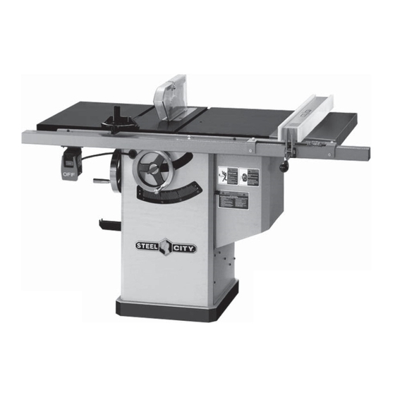
10" RIVING KNIFE CABINET SAW
®
C
US
STEEL CITY TOOL WORKS
VER. 01.11
SHOWN WITH GRANITE TABLE TOP

Model Number

35903
35904
35911
35912
Manual Part No. SC75002

Advertisement

Table of Contents
loading

Summary of Contents for Steel City 35903

  • Page 1: User Manual

    User Manual Read and understand this manual before using machine. 10” RIVING KNIFE CABINET SAW Model Number 35903 35904 SHOWN WITH GRANITE TABLE TOP 35911 ® 35912 STEEL CITY TOOL WORKS VER. 01.11 Manual Part No. SC75002...
  • Page 2: Table Of Contents

    The drawings, illustrations, photographs, and specifications in this user manual represent your machine at time of print. However, changes may be made to your machine or this manual at any time with no obligation to Steel City Tool Works.
  • Page 3: Product Specifications

    PRODUCT SPECIFICATIONS Model No. 35903 Model No. 35904 Model No. 35911 Model No. 35912 Motor Induction Induction Induction Induction 1.75 1.75 Amps 15 / 7.5 15 / 7.5 Volts 120 / 240 120 / 240 Hertz 3450 3450 3450 3450...
  • Page 4: Accessories And Attachments

    ACCESSORIES AND ATTACHMENTS There are a variety of accessories available for your Steel City Product. For more information on any accessories associated with this and other machines, please contact your nearest Steel City distributor, or visit our website at : www.steelcitytoolworks.com.
  • Page 5: Feature Identification

    FEATURE IDENTIFICATION A) Miter Gauge B) Blade Guard Assembly with riving knife C) Motor Cover D) Bevel Scale E) Height Adjustment Handwheel F) Bevel Adjustment Handwheel G) Fence Hooks (2) H) On/Off Switch (Shown with optional fence and table board)
  • Page 6: General Safety

    GENERAL SAFETY WARNING WARNING TO AVOID serious injury and damage to the machine, read and follow all Safety and Operating Instructions before assembling and operating this machine. This manual is not totally comprehensive. It does not Exposure to the dust created by power sanding, saw- and can not convey every possible safety and opera- ing, grinding, drilling and other construction activities tional problem which may arise while using this...
  • Page 7 11. DO NOT FORCE the machine to perform an opera- WARNING tion for which it was not designed. It will do a safer and higher quality job by only performing operations for which the machine was intended. 12. DO NOT stand on a machine. Serious injury could result if it tips over or you accidentally contact any 3.
  • Page 8: Product Safety

    9. DO NOT handle the plug or table saw with wet hands. 10. USE accessories only recommended by Steel City. 11. DO NOT pull the table saw by the power cord. 4. TO REDUCE the risk of electrical shock. DO NEVER allow the power cord to come in contact NOT use this machine outdoors.
  • Page 9: Electrical Requirements

    This manual is written for four specific models, ④ YELLOW ④ WHITE YELLOW Model No 35903,35904,35911 and 35912. Please follow the specific requirements for your model saw. MODEL NO 35904, 3 5912 MODEL NO 35903, 35911 The switch provided with your saw is a magnetic switch designed for 240 volt single phase usage only.
  • Page 10: Grounding Instructions

    240 VOLT OPERATION ONLY The motor supplied with your machine is either a 25' LONG 50' LONG 100' LONG 120/240 dual voltage motor (Model 35903 & 35911) or a 0 to 6 Amps 18 AWG 18 AWG 16 AWG dedicated 240 volt, single phase motor (Model 35904 &...
  • Page 11: Unpacking & Inventory

    If any parts are missing, do not attempt to plug in the power cord and turn "ON" the machine. The machine should only be turned "ON" after all the parts have been obtained and installed correctly. For missing parts, contact Steel City at 1-877-SC4-TOOL.
  • Page 12 AB) M4 x 8mm ROUND HD TAP SCREW (2) AC) WRENCH HOOK AD) 1/4-20 x 3/8 " ROUND HD TAP SCREW (4) AE) FENCE BRACKET (2) 35903 & 35904 CAST IRON TABLE ONLY AH) Cast Iron Wings (2) AJ) M8 FLAT WASHER (8)
  • Page 13: Assembly

    ASSEMBLY HANDWHEEL ASSEMBLY WARNING • The table saw is a heavy machine; two people may be WARNING required for certain assembly operations. MAKE CERTAIN THAT THE SAW IS DISCONNECT- • DO NOT assemble the table saw until you are sure the ED FROM THE POWER SOURCE.
  • Page 14: Section 12 Adjustments

    WRENCH AND FENCE HOOK Fig. 5 ASSEMBLY WARNING MAKE CERTAIN THAT THE SAW IS DISCONNECT- ED FROM THE POWER SOURCE. Fig. 4 Fig. 6 1. Assemble both of the fence hooks (A) to the left side of the cabinet (B) using four 1/4-20 x 3/8"(4) round head screws.
  • Page 15 CAST IRON EXTENSION WING Fig. 8 ASSEMBLY - 35903 & 35904 ONLY WARNING MAKE CERTAIN THAT THE SAW IS DISCONNECT- ED FROM THE POWER SOURCE. CAUTION: The cast iron extension wing is heavy; two people are required for assemble 1. Before installing the extension wings on the table saw, thread the four M x 8mm set screws (A) into the threaded holes in the wings.
  • Page 16 3. Find some help for lifting the extension table. Line up . Use a straight edge across to the main table and both slots with the support bar until the extension extension wing, checking the flatness of both main table reaches the main table. Make sure the (3) 5/1 - and extension table.
  • Page 17: Blade Assembly

    BLADE ASSEMBLY INSTALLING AND REMOVING THE RIVING KNIFE 1. Line up the riving knife in the proper direction to the WARNING mounting bracket(B). SEE FIG 15. MAKE CERTAIN THAT THE SAW IS DISCONNECT- 2. Push the Riving Knife all the way down into the ED FROM THE POWER SOURCE.
  • Page 18 Fig. 18 Riving knife to blade adjustment 1.Riving knife to blade c learance: the gap between the riving knife and the saw blade should be an even distance across the entire radius. SEE FIG 20. Fig.20 3 . Place a square( N) onto the saw blade and against the splitter assembly(O).Make sure the splitter is square to table .SEE FIG.18...
  • Page 19: Section 13 Operations

    CONNECTING SWITCH CORD 3. Pull slack in switch cord into the cabinet. TO MOTOR CORD Make sure that the power cord inside of the cabinet is properly routed and clear of the saw blade and any FOR 230V OPERATION SEE PAGE 13 pinch points for all blade height and blade angle settings WARNING MAKE CERTAIN THAT THE SAW IS DISCONNECT-...
  • Page 20: Adjustments

    ADJUSTMENTS To tilt the blade bevel to 45-degrees, loosen the hand- RAISING AND LOWERING THE wheel lock knob (counterclockwise) and turn the hand- BLADE wheel clockwise. When the saw blade is at 45-degrees it will come into contact with the adjustable positive stop Fig.
  • Page 21 Fig. 26 1. Raise the saw blade to its highest point. 2. Place a combination square (A) on the saw table with one edge (B) of the square against the left miter slot (C). SEE FIG 27. 3. Adjust the square so the rule (D) just touches the saw blade.
  • Page 22: Changing The Saw Blade

    Fig. 29 BEVEL ARROW ADJUSTMENT 1. Make certain that the blade is at 90-degrees to the table surface with a combination square. Fig. 31 1. To align the blade parallel to the miter slot, first loosen two hex head screws (A) under the left side of the table saw.
  • Page 23: Changing Motor Voltage

    Using This section only applies to Model 35903 / both blade wrenches as previously mentioned, 35911 with the 1-3/4HP Motor. The 35904 /...
  • Page 24: Miter Gauge Adjustment

    ADJUSTING POSITIVE STOPS 1. Make sure the switch is "OFF" and disconnect power cord from power source. Fig. 36 2. Open motor cover and verify on the motor tag that motor is dual voltage. 3. If motor tag states that it is dual voltage remove junction box cover (A) on motor (B).
  • Page 25: Operations

    1. First remove the access panel on the left side of Fig. 38 the saw cabinet. SEE FIG. 37 Fig. 37 3)Tighten the 5mm hex head bolts(B ) slightly. Correct adjustment is when a good snug sliding fit is obtained without any side play or movement between the mating dovetail surfaces.
  • Page 26: Section 14 Maintenance

    WARNING 5. Using a padlock (not provided), it is possible to lock the switch to prevent unauthorized use. Lift the red The following section was designed to give "OFF" paddle and place a padlock through the instructions on the basic operations of this table holes (C) in the side of the "ON"...
  • Page 27: Blade Selection

    Combination Blade: Used for cutting with and BLADE SELECTION across the grain. A compromise between a rip blade Choosing the correct blade for the job is essential for and a cross-cut blade, a 10 combination blade will " the safe and efficient use of your table saw. Ignoring typically have between 40-50 teeth.
  • Page 28 CROSSCUTTING RIPPING Crosscutting means cutting across the grain of the Ripping means to cut with the grain of the wood. In wood. In wood products without grain (i.e. MDF, other materials such as MDF or plywood, ripping particleboard), crosscutting simply means cutting simply means to cut lengthwise.
  • Page 29: Dado Operations

    Do not stand directly behind the workpiece when WARNING ripping. SEE FIG 45. Dado operations present very real hazards Fig. 45 requiring proper procedures to avoid serious injury. The chance of kickback is always greater when dado blades are used so extra precautions must be used.
  • Page 30: Maintenance

    MAINTENANCE To clean and maintain the unpainted cast iron BACKLASH ADJUSTMENTS FOR surfaces: BLADE RAISING/LOWERING AND • Apply a heavy coat of WD-40 onto the unpainted BLADE TILTING ASSEMBLIES cast iron surface. If any play is detected in the blade raising/lowering or •...
  • Page 31: Troubleshooting Guide

    TROUBLESHOOTING GUIDE This section covers the most common processing problems encountered in sawing and what to do about them. Do not make any adjustments until the table saw is unplugged and moving parts have come to a complete stop. PROBLEM LIKEL CAUSE(S) SOLUTION 1.Overload tripped.
  • Page 32: Parts

    PARTS LIST...
  • Page 33 M4 x 10mm PAN HD SCREW ¡ ¡ ¡ ¡ SC10164 TABLE INSERT LEFT PAD CAST IRON TABLE FOR 35903 / 35904 ONLY ¡ SC10165 TABLE INSERT RIGHT PAD SC10152 MITER GAUGE ASSY (#30~#46) OR91789 1/4-28 x 3/8" NYLOK SET SCREW...
  • Page 34 146( 2) 148( 2) 149( 2) 156( 2) 157( 2) 165( 2) 166( 2) 167( 2) 170( 2) 171( 2) 180( 3) 172( 2) 173( 2) 174( 2) 175( 2) 200( 2) 201( 2) 202( 2) 217( 2) 218( 2) 219( 2) 221( 2) 222( 2)
  • Page 35 PART PART SC10174 HANDWHEEL ASSY (35903/35911 ONLY) SC80104 M6 x 10mm HEX HD SCREW SC80413 M5 x 25mm ROUND HD SCREW OR90308 M8 x 30mm HEX HD SCREW SC82112 M5 FLAT WASHER (5.4 x 18 x 3) OR91816 M6 x 8mm HEX SOC SET SCREW OR91762 1/4-20 x 1/4"...
  • Page 37 PART PART DESCRIPTION DESCRIPTION OR91726 7/8" x 1/2" WRENCH 1.75 HP FOR 35903/35911 ONLY OR91727 OPEN END WRENCH OR91062 SWITCH SUPPORT OR90290 3mm ALLEN WRENCH SC80104 M6 x 10mm HEX HD SCREW OR90291 4mm ALLEN WRENCH OR90381 M5 HEX NUT...

This manual is also suitable for:

359043591135912

Table of Contents