
Related Manuals for Steel City 20-302


Summary of Contents for Steel City 20-302
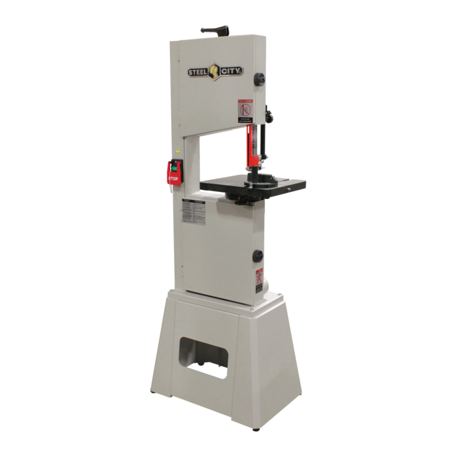
- Page 1 MAnUAL 14’’ BAND SAW 20-302 For technical support, provide the following model and serial numbers: Model No: ______________________ Serial No: ______________________...
- Page 2 The manufacturer warrants its machines to be free from defects in workmanship and materials for a period of 2 years from the date of the original purchase for Steel City shop machines or for a period of 1 year for Titanium production machines;...
-
Page 3: Table Of Contents
The drawings, illustrations, photographs, and specifications in this user manual represent your machine at time of print. However, changes may be made to your machine or this manual at any time with no obligation to Steel City. ProDUCT sPeCIFICATIons Motor... -
Page 4: Safety
sAFeTY This manual is not totally comprehensive. It does not and can not convey every possible safety and operational problem which may arise while using this machine. The manual will cover many of the basic and specific safety procedures needed in an industrial environment. wArnInG All federal and state laws and any regulations having jurisdiction covering the safety requirements for use of this... - Page 5 22. Do noT operate any machine or tool if under the 4. Prevent electrical shock. Follow all electrical and safety codes, including the National Electrical Code (NEC) and influence of drugs, alcohol, or medication. the Occupational Safety and Health Regulations 23.
-
Page 6: Product Safety
ProDUCT sAFeTY 1. Replace any blade which, while rotating, has a back and 3. While using, do not bring your fingers any closer than forth movement over average. Generally, a bad welding 2” to the blade. Use a push stick or pull the piece from is in cause and blades break quickly. -
Page 7: Electrical And Grounding Instructions
eLeCTrICAL AnD GroUnDInG InsTrUCTIons wArnInG IMProPer eLeCTrICAL ConneCTIon equipment-grounding conductor can result in risk of electric To reduce the risk of electric shock, follow all shock. The conductor with the green insulation (with or electrical and safety codes, including the without yellow stripes) is the equipment-grounding National Electric Code (NEC) and the conductor. -
Page 8: Unpacking And Inventory
UnPACKInG & InVenTorY wArnInG DeGreAsInG This machine is heavy, more In order to prevent any corrosion during transport, an antirust has been applied. Above all, greasy surfaces than one person is required to should be wiped clean and cleaned with a clean cloth and unpack and lift. -
Page 9: Assembly
AsseMBLY wArnInG Make sure the switch is in the off position and the machine is unplugged. ◊ BAse AsseMBLY ◊ sAw AsseMBLY 1. With the help of another person, install the saw on the base and attach it to the base by using hex bolts on each corner. - Page 10 5. Open the lower access door. The drive belt is already inside, on the saw shaft. Check if the motor pulley is in Stop line with the saw pulley. If required, loosen the set screw on the motor shaft so you can slide the motor pulley to align it with the saw pulley, and tighten the set screw to lock in place.
-
Page 11: Adjustments
ADJUsTMenTs wArnInG Make sure the switch is in the off position and the machine is unplugged. We will do a blade replacement to show the various adjustments required. ◊ BLADe rePLACeMenT 1. Release blade tension by lifting blade tension handle. It might be necessary to turn the handle counterclock- wise for the blade to be loose enough to be removed easily. - Page 12 ◊ BLADe GUIDAnCe AnD CUTTInG ◊ CHAnGInG BLADe sPeeD HeIGHT We offer 2 blade speeds, low and high (2300 or 3200 lin.ft./min). Both the upper and lower guide block assemblies must 1. Open the lower door to access the wheel. be adjusted after each blade replacement and after 2.
- Page 13 ◊ MITer sLoT PArALLeLIsM The miter slot must be parallel to the blade as much as noTe : This process will get the miter slot close possible. This allows the miter gauge to slide parallel to to being parallel with the blade, improving angled the blade so you get some precision on miter cuts.
-
Page 14: Maintenance
MAInTenAnCe ◊ CLeAnInG BrUsH wArnInG A cleaning brush is installed to prevent pitch and saw- Make sure the switch is in the off position and dust build up on the lower wheel. Verify that the brush the machine is unplugged. keeps the lower wheel tire clean at all times. -
Page 15: Parts List
PArTs LIsT Page 15... - Page 16 Page 16...
- Page 17 Page 17...
- Page 18 !"#$#"%#% !"#$#"%$& !"#$#"%#" !"#$#"%$' !"#$#"%#$ !"#$#"%$( !"#$#"%#& !"#$#"%$) !"#$#"%#' !"#$#"%$* !"#$#"%#( !"#$#"%+# !"#$#"%#) !"#$#"%+% !"#$#"%#* !"#$#"%+" !"#$#"%#+ !"#$#"%+$ !"#$#"%%# !"#$#"%++ !"#$#"%%% !"#$#"%+& !"#$#"%%& !"#$#"%+' !"#$#"%%' !"#$#"%+( !"#$#"%%( !"#$#"%+) !"#$#"%%) !"#$#"%+* !"#$#"%%* !"#$#"%&# !"#$#"%%+ !"#$#"%&" !"#$#"%"# !"#$#"%&", !"#$#"%"% !"#$#"%&$ !"#$#"%"" !"#$#"%&+ !"#$#"%"$ !"#$#"%&&...
- Page 19 !"#$#""#% !"#$#"%#& !"#$#""%& !"#$#"%#" !"#$#""%' !"#$#"%#$ !"#$#""%( !"#$#"%#' !"#$#"""% !"#$#"%#( !"#$#"$#% !"#$#"%#) !"#$#"$#$ !"#$#"%#* !"#$#"$#) !"#$#"%#+ !"#$#"$#* !"#$#"%#, !"#$#"$#+ !"#$#"%&& !"#$#"$%# !"#$#"%&) !"#$#"$%% !"#$#"%&* !"#$#"$%" !"#$#"%&+ !"#$#"$%$ !"#$#"$%' !"#$#"$%( !"#$#"$"& !"#$#"$"' !"#$#"$"( !"#$#"$"+ !"#$#"$$# !"#$#"$$" Page 19...
- Page 20 noTes Page 20...
Need help?
Do you have a question about the 20-302 and is the answer not in the manual?
Questions and answers