Sign In
Upload
Manuals
Brands
Teledyne Manuals
Digital Camera
Princeton Instruments NIRvana HS
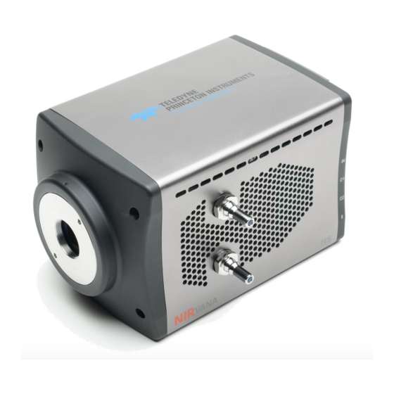
Teledyne Princeton Instruments NIRvana HS Manuals
Manuals and User Guides for Teledyne Princeton Instruments NIRvana HS. We have
1
Teledyne Princeton Instruments NIRvana HS manual available for free PDF download: System Manual
Teledyne Princeton Instruments NIRvana HS System Manual (107 pages)
Brand:
Teledyne
| Category:
Digital Camera
| Size: 8.85 MB
Table of Contents
Table of Contents
5
Chapter 1: About this Document
11
Intended Audience
11
Intended Use of Equipment
11
Related Documentation
11
Table 1-1: Related Documentation
11
Document Organization
12
Safety Related Symbols Used in this Manual
13
Safety Related Symbols on Equipment
13
Nirvana HS Safety Information
14
Precautions
14
Chapter 2: Nirvana HS Camera System
15
Figure 2-1: Nirvana HS Camera System: Standard Items
15
Nirvana HS Camera
16
Focal Plane Array (FPA) Sensor
16
Figure 2-2: Typical Nirvana HS Camera
16
Window
17
Cooling
17
Internal Fan
17
External Coolant Circulator
18
Coolant Ports
18
Rear-Panel Connectors
19
Figure 2-3: Nirvana HS Rear-Panel Connectors
19
Table 2-1: Nirvana HS Rear-Panel Connectors
19
Power Supply
20
Standard Cables
21
Table 2-2: Standard Nirvana HS Camera System Cables
21
Optical Mounts
22
Coolant Hoses
22
Certificate of Performance
22
Figure 2-4: Available Optical Adapters
22
Application Software
23
Accessories
23
Unpack the System
23
2.10 Care and Cleaning of a Nirvana HS System
24
Detector Window
24
Cleaning
24
Camera
24
Optical Surfaces
24
2.11 Repairs
24
Chapter 3: Install Lightfield
25
Prerequisites
25
Installation Procedure
25
Chapter 4: System Block Diagrams
27
Figure 4-1: Typical Imaging Experiment Layout: Air-Cooled Camera
27
Figure 4-2: Typical Spectroscopy Experiment Layout: Air-Cooled Camera
27
Figure 4-3: Typical Imaging Experiment Layout: Air/Liquid-Cooled Camera
28
Figure 4-4: Typical Spectroscopy Experiment Layout: Air/Liquid-Cooled Camera
28
Chapter 5: Hardware Configuration
29
Attach Lens to the C-Mount Adapter
29
Adjusting the C-Mount Adapter
29
Figure 5-1: Adjustable C-Mount Adapter
30
Mounting the Camera
31
External Coolant Circulator Use
32
Figure 5-2: Coolant Input/Output Port Identification
32
Experiment Shutdown
33
Chapter 6 First Light
35
Figure 6-1: Block Diagram: Nirvana HS Light Path
35
Imaging Applications
37
Figure 6-2: Typical Devices Tab: Imaging Application
37
Figure 6-3: Typical Experiment Devices Area: Adding Nirvana HS Camera
38
Figure 6-4: Typical Workspace: Nirvana HS Camera
38
Data Acquisition
39
Figure 6-5: Typical Imaging Application Workspace: View Tab
39
Figure 6-6: Typical Imaging Application View Tab: Image Display
39
Shut down Procedure
40
Spectroscopy Applications
41
Figure 6-7: Typical Devices Tab: Spectroscopy Application
42
Figure 6-8: Typical Experiment Devices Area: Adding Nirvana HS and
42
Figure 6-9: Typical Workspace: Nirvana HS Camera with Spectrograph
43
Rotational Alignment and Focus
44
Rotational Alignment
45
Figure 6-10: Typical Spectroscopy Application Workspace: View Tab
45
Figure 6-11: Experiment Options ► Align Spectrometer Selection
46
Figure 6-12: Align Spectrometer: Pre-Rotational Alignment
46
Focus
47
Figure 6-13: Align Spectrometer: Post-Rotational Alignment
47
Acquire Data
48
Shut down Procedure
48
Chapter 7 Exposure
49
Exposure Time
49
Saturation
49
Noise Sources
50
Dark Charge
50
Sensor Temperature
50
Chapter 8 Readout
53
Modes
53
Figure 8-1: Typical Readout Expander
53
Full Frame Readout
54
Figure 8-2: Typical Analog to Digital Conversion Expander
54
Expose During Readout
55
Figure 8-3: Timing Diagram: Full Frame Readout, T Exp > T Ro
55
Exposure Time Is Longer than or Equal to Readout Time
56
Figure 8-4: Timing Diagram: Expose During Readout, T Exp ≥ T Ro
56
Exposure Time Is Shorter than Readout Time
57
Figure 8-5: Timing Diagram: Frame Transfer Readout, T Exp < T Ro
57
Full Frame Readout Versus Expose During Readout
58
Determine the Best Readout Mode for an Application
59
Region of Interest Strategy
59
Region of Interest Sizing Guidelines
59
Single Region of Interest Placement Guidelines
60
Two to Four Regions of Interest Placement Guidelines
60
Regions of Interest Impact on Frame Rate
60
Figure 8-6: Vertically Stacked Rois with Small Vertical Gap
61
Figure 8-7: Vertically Stacked Rois with Large Vertical Gap
61
Figure 8-8: Horizontally Aligned Rois with Large Horizontal Gap
62
Figure 8-9: Vertically Aligned Rois with Small Horizontal Gap
62
Figure 8-10: Vertically Aligned MID-Sensor Rois with Large Horizontal Gap
63
Figure 8-11: Vertically Offset Rois with Large Horizontal Gap, Overlapping Rows
63
Figure 8-12: Vertically Offset Rois with Large Horizontal Gap, no Vertical Gap or
64
Figure 8-13: Vertically Offset Rois with Large Horizontal Gap, 4 Row Vertical Gap
64
Number of Regions of Interest
65
Figure 8-14: Three Rois with Horizontal Gaps and Overlapping Rows
65
Figure 8-15: Excessive Number of Small Regions of Interest
65
Analog Gain
66
Software Binning
66
Digitization
67
Speed
67
Figure 8-16: Typical Analog to Digital Conversion Expander
67
ADC Offset (Baseline Offset)
68
Chapter 9 Data Correction
69
Non-Uniformity Correction (NUC): Gain and Offset
69
Background Subtraction
69
Flatfield Correction
70
Figure 9-1: Typical Online Corrections Expander: Background Subtraction
70
Figure 9-2: Typical Online Corrections Expander: Flatfield Correction
70
Defect/Blemish Correction
71
Figure 9-3: Typical Star Defect (Not to Scale)
71
Chapter 10: Advanced Topics
73
10.1 Shutter Control Modes
73
10.2 Trigger Response Modes
74
External Trigger Input
74
Figure 10-1: Nirvana HS Camera: Rear Panel
74
No Response
75
Readout Per Trigger
75
Figure 10-2: Timing Diagram: no Response Mode
75
Figure 10-3: Timing Diagram: Readout Per Trigger
75
Expose During Trigger Pulse
76
Start on Single Trigger
76
Figure 10-4: Timing Diagram: Expose During Trigger Pulse
76
10.3 Output Signal Control
77
Figure 10-5: Timing Diagram: out 1/OUT 2 Control
77
Appendix A: Technical Specifications
79
System Dimensions and Weight
79
Vacuum Window
79
Camera Specifications
79
Table A-1: General System Specifications
79
Table A-2: Nirvana HS FPA Specifications
79
Thermal Characteristics
80
Power Specifications
80
Table A-3: Operating Temperatures
80
Environmental Specifications
81
Ventilation
81
External Coolant Circulator Specifications
81
Table A-4: Power Specifications
81
Table A-5: Nirvana HS Environmental Specifications
81
Table A-6: External Coolant Circulator Specifications
81
Minimum Host Computer Specifications
82
Appendix B: Outline Drawings
83
Figure B-1: Outline Drawing: Nirvana HS with C-Mount
83
Figure B-2: Outline Drawing: Nirvana HS with Spectroscopy-Mount
84
Appendix C: Optical Mount Removal and Replacement
85
Figure C-1: Nirvana HS with Optical Mount Facing up and Camera Bottom
86
Figure C-2: Retaining Hardware Securing Optical Mount to Camera Chassis
86
Optical Mount Reference Drawings
87
Figure C-3: Optical C-Mount Reference Exploded View
87
Figure C-4: Optical Spectroscopy-Mount Reference Exploded View
88
Appendix D: Calibration Charts
89
Figure D-1: Hg Spectrum: Nirvana HS 1.7/SP-2500
90
Figure D-2: Ne/Ar Spectrum: Nirvana HS 1.7/SP-2500
91
Appendix E: Troubleshooting
93
Baseline Signal Suddenly Changes
93
Camera Stops Working
93
Table E-1: Issues with Recommended Troubleshooting Guidelines
93
External Coolant Circulator: Low Coolant (Air in the Hoses)
94
Cooling Troubleshooting
95
Temperature Lock Cannot be Achieved or Maintained
95
Gradual Deterioration of Cooling Capability
95
Device Is Not Found
96
TEC Fault LED Comes on
96
Figure E-1: Typical Load Experiment: Devices Missing Dialog
96
Warranty and Service
97
Limited Warranty
97
Basic Limited One (1) Year Warranty
97
Limited One (1) Year Warranty on Refurbished or Discontinued Products
97
XP Vacuum Chamber Limited Lifetime Warranty
97
Sealed Chamber Integrity Limited 12 Month Warranty
98
Vacuum Integrity Limited 12 Month Warranty
98
Image Intensifier Detector Limited One Year Warranty
98
X-Ray Detector Limited One Year Warranty
98
Software Limited Warranty
98
Owner's Manual and Troubleshooting
99
Your Responsibility
99
Contact Information
100
Row Overlap64
103
Identified 86
104
Table 8-1: Full Frame Readout Vs. Expose During Readout Frame Rate Comparison
105
Advertisement
Advertisement
Related Products
Teledyne Princeton Instruments Sophia-XO
Teledyne Princeton Instruments PI-MTE
Teledyne Princeton Instruments Nano-XF
Teledyne Princeton Instruments NIRvana
Teledyne Princeton Instruments Quad-RO
Teledyne Princeton Instruments PI-MAX 3
Teledyne ProEM Series
Teledyne ProEM:512BK
Teledyne ProEM:1600
Teledyne ProEM:1024B
Teledyne Categories
Measuring Instruments
Analytical Instruments
Digital Camera
Test Equipment
Laboratory Equipment
More Teledyne Manuals
Login
Sign In
OR
Sign in with Facebook
Sign in with Google
Upload manual
Upload from disk
Upload from URL