
Related Manuals for Air Techniques SensorX


Summary of Contents for Air Techniques SensorX
- Page 1 SensorX Installation and Operating Instructions 2121100020L29 *2121100020L29*...
-
Page 3: Table Of Contents
12 Maintenance ..... SensorX Size #1 ... . . SensorX Size #2 ... . . - Page 4 Contents Appendix 14 Recommended exposure times ..15 Handover record ....2121100020L29 2101V007...
-
Page 5: Important Information
These installation and operating instructions are – CAUTION an integral part of the unit. Risk of minor injuries Air Techniques shall not be held liable and – NOTICE offers no guarantees of the safe and Risk of extensive material/property damage... -
Page 6: Copyright Information
Health Industry Bar Code (HIBC) ing Instructions, including excerpts thereof, may only be carried out with the written approval of Authorized EU representative EC REP Air Techniques. Manufacturer Date of manufacture Dispose of correctly in accordance with EU Directive 2012/19/EU (WEEE). -
Page 7: Safety
Improper use and repair work must be carried out either by Any other usage or usage beyond this scope is Air Techniques personnel or by a suitably quali- deemed to be improper. The manufacturer fied person approved by Air Techniques. -
Page 8: Essential Performance Charac- Teristics
NOTICE Notification requirement of Negative effects on the EMC due to serious incidents non-authorized accessories Use only Air Techniques accessories or ❯ The operator/patient has to report any serious accessories approved by Air incident related the product to the manufacturer Techniques. -
Page 9: Transport
Only the original packaging ensures optimum protection for the unit during transport. If necessary, the original packaging for this unit can be ordered from Air Techniques. Air Techniques cannot be held responsi- ble for any damage resulting from trans- port in unsuitable packaging, even during the warranty period. -
Page 10: Product Description
(possible variations due to country-spe- cific requirements and/or import regulations): Overview SensorX Size #1 ....G9510A – SensorX Size #1, Sensor – Calibration data carrier –... -
Page 11: Consumables
Product description Consumables The following materials are consumed during operation of the unit and must be reordered sep- arately: Hygienic protective covers Size #1 (qty. 100) ......G9550 Hygienic protective covers Size #1 (qty. -
Page 12: Technical Data
Product description Technical data SensorX Size #1 Electrical data Nominal voltage V DC Nominal current Classification FDA classification (CFR Title 21) General technical data Dimensions W x H x D 27.4 x 39.0 x 6.3 1.08 x 1.54 x 0.25 Cable length, sensor 98.43... -
Page 13: Sensorx Size #2
Sensor type CMOS Scintillator Structured CsJ scintillator on fibre-optics Electromagnetic compatibility (EMC) The information on electromagnetic compatibility (EMC) applies to both SensorX Sensor Size #1 and Size #2. Electromagnetic compatibility (EMC) Interference emission measurements Electromagnetic interference radiation Group 1, Class B... - Page 14 Product description Electromagnetic compatibility (EMC) Interference immunity measurements on cover Immunity to interference by high-frequency electromag- netic fields IEC 61000-4-3:2006+A1:2007+A2:2010 Compliant 3 V/m 80 MHz - 2.7 GHz 80% AM at 1 kHz Immunity to interference by near fields of wireless HF communication devices IEC 61000-4-3:2006+A1:2007+A2:2010 Compliant...
-
Page 15: Ambient Conditions
Product description Ambient conditions Ambient conditions during operation Temperature °C 10 - 35 °F +50 to +95 Humidity < 80 Air pressure 750 - 1160 Height above sea level < 2000 < 6562 Ambient conditions during storage and transport Temperature °C -20 to +60 °F... -
Page 16: Model Identification Plate
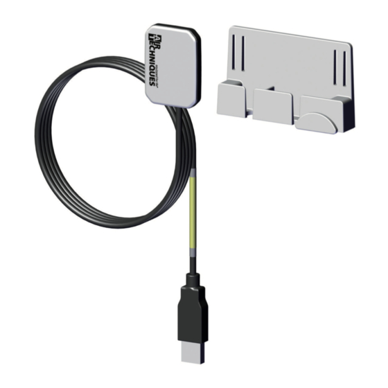
The model identification plate is located on the sensor cable and on the case. Fig. 1: Model identification plate on the sensor cable Fig. 3: SensorX X-ray sensor Fig. 2: Model identification plate on the case Sensor holder Cable holder... -
Page 17: Installation
Installation Installation Requirements Installation/setup room The unit may only be used in a room that has ❯ been set up specifically for this purpose (e. g. an x-ray room). Do not use outdoors. Do not expose the unit to direct sunlight or ❯... -
Page 18: System Requirements
Installation System requirements The system requirements of the software being used to operate the device must always be met during its operation. If third-party software is being used to operate the device, compliance with its system requirements must be assured. The following additional system requirements must also be met: Drive: DVD ROM... -
Page 19: Installation
Installation Fastening the sensor holder with the adhesive Installation Fitting the sensor holder The sensor holder and the cable holder can be secured to the wall or treatment unit using either the adhesive pad or screws and dowel. The sensor holder can also be fitted to the lamp stand using the Velcro strip. -
Page 20: Installation With Visionx
Accept the License Agreement. ❯ IEC 60950‑1 (EN 60950‑1) standard. Select the required components. ❯ Select the SensorX unit. ❯ Connecting the device to a computer Follow the further instructions given by the ❯ installation wizard. -
Page 21: Commissioning And First Start-Up
For further information, see the Help func- tion of VisionX (E7303). Requirements: ü SensorX is connected to computer. Start-up SensorX. ❯ Click on once. ❯ Click Devices. ❯ Click on the SensorX unit in the list. ❯ 2121100020L29 2101V007... -
Page 22: Configuring The Unit In Dbswin
Under Image acquisition device, select the ❯ SensorX is controlled by the VistaNet module. device with which the X-ray images will be In the properties of DBSWIN, the SensorX mod- imported. ule must be inactive. The selection list contains only the image If the ScanX module is not needed (e.g. - Page 23 Installation Drag the SensorX module and if applicable the Activate the connected unit in the Registered ❯ ❯ ScanX module with into the Inactive field. column. Click the Edit button. ❯ Restart DBSWIN. ❯ Configuring the device in ScanX Net Select Start >...
-
Page 24: Commissioning Tests
Installation Testing the device The image quality test is carried out with VisionX Inspect (see VisionX handbook, order An X-ray image can be recorded to test whether number: E7303 (2110200001). the unit has been connected correctly. The following aids are required: Select the Test tab. - Page 25 Installation Analysis NOTICE The test phantom can be damaged if it is dropped. Secure the test phantom so that it ❯ cannot fall down. Alternatively, place the test phantom ❯ on a level surface and insert the tube vertically into the centering rings of the test phantom.
-
Page 26: Usage
Start the imaging software. ❯ age before every use. Select the desired image mode. ❯ Do not use the sensor if it is damaged. ❯ Make SensorX ready for image acquisition in ❯ Use a right-angle holder. ❯ the imaging software. WARNING NOTICE... -
Page 27: 10 Cleaning And Disinfection
Usage 10 Cleaning and disinfection If you use the right-angle technique, make sure ❯ to use a fitting right-angle holder. The right- When cleaning and disinfecting the unit and its angle holder must not damage the hygienic accessories, comply with national directives, protective cover. -
Page 28: Clean And Disinfect The Accesso
Usage 10.1 Clean and disinfect the 11 Reprocessing accessories 11.1 Risk analysis and classifica- The sensor holder surface, the cable and the tion USB connector can be disinfected with disinfec- tant wipes. A risk analysis and classification of medical devi- Wipe the surface with a soft, lint-free cloth ❯... -
Page 29: General Information
In accordance with IEC 80601-2-60, the applied Wear eye protection. part of the SensorX is limited to a length of 80 mm, starting at the sensor edge, opposite from the cable. For this reason, only the applied part Use a mask. -
Page 30: Manual Cleaning, Disinfection
Usage Protect the unit from contamination when Drying ❯ transporting it from the treatment chair to the Allow the device to air-dry. ❯ reprocessing location. The device must be completely dry before a new hygienic protective cover is pulled on. 11.5 Manual cleaning, disinfection and drying... -
Page 31: 12 Maintenance
Usage 12 Maintenance The unit is maintenance-free. 2121100020L29 2101V007... -
Page 32: Troubleshooting
Troubleshooting Troubleshooting 13 Tips for operators and service technicians Any repairs above and beyond routine maintenance may only be done by suitably qualified per- sonnel or by one of our service technicians. 13.1 Poor X-ray image Error Possible cause Remedy No image transmission, X-ray dose too low Correct the exposure values... - Page 33 Troubleshooting Error Possible cause Remedy Error code E-1020 The current state of the sensor Disconnect and reconnect the ❯ does not permit image creation USB connection cable. Sensor defective Inform your Service Techni- ❯ cian. Error code E-1026 Incorrect image mode Select a different image ❯...
- Page 34 Appendix Appendix 14 Recommended exposure times CAUTION Over-long exposure times can render the X-ray image unusable Do not exceed the maximum exposure time of 0.5 s. ❯ The following table lists the exposure times for an adult patient. The exposure time must be increased by 25% for adult patients with a high bone density. The exposure time for children must be reduced by 30%.
- Page 35 Appendix 15 Handover record This document confirms that a qualified handover of the medical device has taken place and that appropriate instructions have been provided for it. This must be carried out by a qualified adviser for the medical device, who will instruct you in the proper handling and operation of the medical device. Product name Order number (REF) Serial number (SN)
- Page 40 Hersteller / Manufacturer: DÜRR DENTAL SE Höpfigheimer Str. 17 74321 Bietigheim-Bissingen Germany www.duerrdental.com Manufactured for / Distributed by: Air Techniques, Inc. 1295 Walt Whitman Road Melville, New York 11747-3062, USA Phone: 800-247-8324 Fax: 888-247-8481 www.airtechniques.com...
Need help?
Do you have a question about the SensorX and is the answer not in the manual?
Questions and answers