Table of Contents
Advertisement
Advertisement
Chapters
Table of Contents
Troubleshooting

Related Manuals for Air Techniques A/T2000 XR


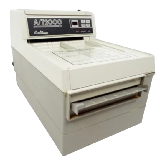
Summary of Contents for Air Techniques A/T2000 XR
- Page 1 AUTOMATIC FILM PROCESSOR S E R V I C E M A N U A L...
-
Page 2: Table Of Contents
TABLE OF CONTENTS Introduction ............3 Product Overview . -
Page 3: Introduction
INTRODUCTION Purpose This document provides the instructions necessary to perform repair and maintenance of the AT2000 XR Automatic Film Processor. It is intended for all recognizable field servicing of the unit and includes procedures to disassemble the unit to access internal components as well as steps necessary to perform preventive maintenance, inspection, cleaning, troubleshooting and removal/replacement of defective parts. -
Page 4: Product Overview
PRODUCT OVERVIEW CONNECTOR (At Rear) ADJUST SET-TEMP POWER SWITCH OPERATOR CONTROLS FILM RECEPTACLE TRAY DIVIDERS FILM INLET WITH ACTIVATING SHUTTER LEVELING FOOT LEVELING BASE BUBBLE REPLENISHMENT LEVEL PUMP AND AGITATOR MOTOR DRAW LEVELING FOOT... -
Page 5: Specifications
SPECIFICATIONS ELECTRICAL 115VAC, 60 Hz, 8 AMPS. Use a 15 AMP, 3 prong, grounded out- let. A separate dedicated 15 AMP line is recommended. WATER FLOW 1/2 gallon per minute water flow (while processing film). WATER PRESSURE 80 PSI maximum / 30 PSI minimum. Water source must have a manual shut-off near processor. -
Page 6: Plumbing Connections - Option 1
PLUMBING CONNECTIONS - OPTION 1 Chemistry recovery and wash water sewer disposal connection. (If permitted by local code.) -
Page 7: Plumbing Connections - Option 2
PLUMBING CONNECTIONS - OPTION 2 Chemistry recovery and wash water sewer disposal connection. (If permitted by local code.) -
Page 8: Plumbing Connections
PLUMBING CONNECTIONS CONNECT TO PLUMBING (See Plumbing Connections - OPTIONS 1 & 2) q Match color-coded drain hoses to corresponding color-coded label on barbed fittings at the rear of the unit. Mount the hose end onto the barbed fitting by rotating the hose clockwise while pushing. -
Page 9: Water Recirculation Option
WATER RECIRCULATION OPTION PLUMBING CONNECTIONS 1. Fill the container with fresh water to the bottom of the WATER label. 2. Cut the wash water drain hose so that when it is inserted into the water container it reaches to the bottom of the WATER label. Insert the hose into the container. 3. -
Page 10: Major Assemblies And Parts
MAJOR ASSEMBLIES AND PARTS ITEM DESCRIPTION PART NUMBER Cover Assembly with Electronic Module 45800 Base Assembly 45200 Developer Transport 45500 Fixer Transport 45505 Wash/ Dry Transport 45510 Leveling Base Assembly 45100 Leveling Feet 43106... -
Page 11: Internal Parts Identification
INTERNAL PARTS IDENTIFICATION PROCESSOR COVER ELECTRICAL PROCESSOR CABLE COVER P/N 45800 RAISED BOSS BAFFLE PLATES INNER BAFFLE P/N 41307 ON LEFT END BOTTOM OF BAFFLE MUST PASS BELOW RAISED BOSS ON SIDE PLATE ACTIVATING WASH/DRY RACK SHUTTER P/N 45510 FIXER RACK (RED) P/N 45505 OUTER BAFFLE... -
Page 12: Operator Controls
OPERATOR CONTROLS The following provides a brief summary description of the operating controls of the AT2000 XR Film Processor. Refer to the Operator's Manual shipped with the product for detailed operation informaion for the AT2000 XR Film Processor. INDICATOR LIGHTS POWER Illuminates when the POWER switch (located on top) is in the ON position. -
Page 13: Function Charts
FUNCTION CHARTS AT2000 XR FUNCTION & OPERATION CHARTS The AT2000 XR Film Processor's function and status conditions, as designed, are separated into six categories listed below. The charts associated will provide insite to required processor operation and expedite any trouble-shooting, if applicable. Refer to the appropriate Function Chart, as required, to quickly identify and resolve the issue at hand. - Page 14 FUNCTION CHARTS FUNCTIONAL MODES DRYER READY NORM ENDO PROC REPLEN MODE DEV TEMP DISPLAY SHUTTER HEATER POWER & LIGHT ARROW ARROW LIGHT PUMP RECIRC Developer Turn ON > -15° F Temperature Closed 100% (90 sec) Heatup Developer Turn ON < 77° F Temperature Closed 100%...
- Page 15 FUNCTION CHARTS CHEMISTRY HEATER ABNORMAL CONDITIONS AND PROTECTION DEVICE STATE or HEATER DEVICE DISPLAY HEATER TEMPERATURE CONTROL Thermistor -15°F OPEN (SEE NOTE 1) (SEE NOTE 2) Thermistor SHORT or > 99°F 99°F Developer Temp Thermistor < -15°F (SEE NOTE 3) Thermistor Condition Thermistor Set Point to 99°F...
- Page 16 FUNCTION CHARTS HEATER PAD POWER CONTROL General Note: The theroetical heating rate of the chemistry is approximately 0.7°F/min ( 1°F/min). The actual heating of chemistry may be different due to thermal inertia. HEATER POWER PERCENTAGE For Heating rate DEVELOPER NEON TEST LAMP (SEE NOTE 1) TEMPERATURE Placed Across...
- Page 17 FUNCTION CHARTS REPLENISHER RATES FOR DEVELOPER AND FIXER STANDARD (DOMESTIC) AT2000 XR FILM PROCESSOR FILM SHUTTER PUMP MODE FLUID VOLUME LENGTH Open Time On Time (ml) (oz) POWER Turn ON 0 inch 0 min 0 sec 90 sec 4.26 POWER Turn ON - CLEANING Mode 0 inch 0 min 0 sec 0 sec...
-
Page 18: Measuring Replenisher Dispensing
MEASURING REPLENISHER DISPENSING The following provides an approach to verifying the replenisher pump output flow rate for developer and fixer chemistry. This technique will aid in solving replenisher related problems. Equipment needed: 250ml Graduated Beaker and Stopwatch Initial Procedure 1. Verify the electronics are operating as required before starting a replenishment rate examination. -
Page 19: Electrical Diagrams And Test Points
ELECTRICAL DIAGRAMS AND TEST POINTS AT2000 XR Electrical Diagrams & Test Points Wiring, test point and thermistor resistance information for the AT2000 XR Film Processor is provided in this section. The associated charts/diagrams identify all serviceable features and provide the required parameters to facilitate equipment troubleshooting. Refer to the appropriate information as required to quickly identify and resolve the equipment fault issue. - Page 20 SYSTEM SCHEMATIC...
- Page 21 CONNECTOR DIAGRAMS CONNECTOR COMPARTMENT COVER. REMOVE TO ACCESS J2, J3, J4, J5 TAKE J1 MEASUREMENTS HERE TO TEST COMPONENT VOLTGAGE / RESISTANCE PER TEST POINT CHART. THERMISTOR WATER SENSOR HEATER PAD DRIVE MOTOR...
- Page 22 THERMISTOR RESISTANCE CHART Bath Temp Thermistor Bath Temp Thermistor Bath Temp Thermistor Bath Temp Thermistor (° Resistance (° Resistance (° Resistance (° Resistance 7658 5941 4651 3668 7642 5797 4540 3583 7274 5655 4432 3501 7089 5516 4328 3420 6911 5382 4225 3343...
-
Page 23: Troubleshooting
TROUBLESHOOTING AT2000 XR troubleshooting guide is provided in two categories for quick access to problems that are specifically electro-mechanical in nature, and problems specifically relating to film quality. Other equipment faults can also be resolved using the troubleshooting section provided in the processor User’s Manual. Section 1: Intended for the diagnosis and/or repair of faults relating to electro-mechanical operation/function for the AT2000 XR Film Processor. -
Page 24: Processor Is Totally Inactive
TROUBLESHOOTING AT 2 0 0 0 X R O p e r a t i o n & F u n c t i o n Tr o u b l e s h o o t i n g 1. -
Page 25: Processor Stops Mid-Cycle
TROUBLESHOOTING AT 2 0 0 0 X R O p e r a t i o n & F u n c t i o n Tr o u b l e s h o o t i n g 4. -
Page 26: Dryer Fan / Air Heater Problems
TROUBLESHOOTING AT 2 0 0 0 X R O p e r a t i o n & F u n c t i o n Tr o u b l e s h o o t i n g 7. -
Page 27: Chemistry Temperature Control Problems
TROUBLESHOOTING AT 2 0 0 0 X R O p e r a t i o n & F u n c t i o n Tr o u b l e s h o o t i n g 10. -
Page 28: Wash Water Problems
TROUBLESHOOTING AT 2 0 0 0 X R O p e r a t i o n & F u n c t i o n Tr o u b l e s h o o t i n g 12. -
Page 29: Section 2 Film Quality Troubleshooting
TROUBLESHOOTING SECTION 2. AT2000 XR Film Quality Troubleshooting This trouble shooting section is intended for the diagnosis issues relating to film processing anomalies for the AT2000XR film processors. The itemized list below is a summary of issues, for the complete diagnosis and/or repair of the issue exhibiting refer to the subsequent pages as identified. -
Page 30: Films Are Too Dark Or Grainy
TROUBLESHOOTING AT 2 0 0 0 X R F i l m Q u a l i t y Tr o u b l e s h o o t i n g 1. FILMS ARE TOO DARK or GRAINY A. -
Page 31: Films Are Too Light
TROUBLESHOOTING AT 2 0 0 0 X R F i l m Q u a l i t y Tr o u b l e s h o o t i n g 2. FILMS ARE TOO LIGHT A. Confirm the following initial requirements for AT2000XR Automatic film processing; 1. -
Page 32: Film Density / Contrast Is Poor
TROUBLESHOOTING AT 2 0 0 0 X R F i l m Q u a l i t y Tr o u b l e s h o o t i n g 3. FILM DENSITY / CONTRAST IS POOR A. -
Page 33: Film Has Streaking Consistently Repeating
TROUBLESHOOTING AT 2 0 0 0 X R F i l m Q u a l i t y Tr o u b l e s h o o t i n g 5. FILM HAS STREAKING CONSISTENTLY REPEATING A. Confirm the following initial requirements for AT2000XR Automatic film processing; 1. -
Page 34: Film Has Spots / Appears Dirty
TROUBLESHOOTING AT 2 0 0 0 X R F i l m Q u a l i t y Tr o u b l e s h o o t i n g 7. FILM HAS SPOTS / APPEAR DIRTY A. -
Page 35: Film Has Silver / Green / Brown Color
TROUBLESHOOTING AT 2 0 0 0 X R F i l m Q u a l i t y Tr o u b l e s h o o t i n g 9. FILM HAS SILVER / GREEN / BROWN COLOR A. -
Page 36: Film Emulsion Is Peeling Off
TROUBLESHOOTING AT 2 0 0 0 X R F i l m Q u a l i t y Tr o u b l e s h o o t i n g 11. FILM EMULSION IS PEELING OFF A. Confirm the following initial requirements for AT2000XR Automatic film processing; 1. -
Page 37: Avoiding Chemistry Contamination
AVOIDING CHEMISTRY CONTAMINATION Contamination of developer chemistry is one of the most common problems associated with x-ray film processors. The source of contamination must be identified to prevent this problem from happening again. Once contaminated developer is diagnosed, tanks and rack assemblies must be cleaned with Formula 2000 Plus, (Part Number: 43965). -
Page 38: Cover Assembly
COVER ASSEMBLY COVER ASSEMBLY 45800 ITEM DESCRIPTION PART NUMBER Electonics Module 45415 Dryer Heater Assembly 43330 Dryer Fan 43530 Air Heater Assembly 43811 Molded Cover 45360 Cover Insert w/ Light Seal 45351 Shutter Assembly 43584 Film Sensor Assembly 44482 Shutter Guard 43658 Hinge Block 43587... - Page 39 COVER ASSEMBLY DETAIL B DETAIL C Film Sensor Optic Switch Adjustment Screws for PCB Cross Section View NOTE: Film shutter flag (item 7) must reside in optic sensor (on PCB) when inactive, see detail "C" for view. Improper alignment results in "STAYS INPROCESS MODE" DETAIL D Main Bracket Assembled Interlock...
-
Page 40: Base Assembly - Top View
BASE ASSEMBLY - TOP VIEW OVERHEAD VIEW BASE ASSEMBLY 45200 DETAIL A... - Page 41 BASE ASSEMBLY - TOP VIEW ITEM DESCRIPTION PART NUMBER Screw - Drive Block Mount 30569 Interlock Post 45323 Drain Tube Washer 43271 Drain Tube Assembly - Black (includes item 2) 43286 Drain Tube Assembly - Red (includes item 2) 43287 Drain Tube - Wash 43270 Screw - Gear Cover...
-
Page 42: Base Assembly - Bottom View
BASE ASSEMBLY - BOTTOM VIEW SINGLE FUSE CONFIGURATION... - Page 43 BASE ASSEMBLY - BOTTOM VIEW ITEM DESCRIPTION PART NUMBER Solenoid Assembly 43980 Fuse Holder 90219 Line Cord IEC Connector w. EMI Filter 45975 Fuse, Delayed Action, 8 Amp, Box of 5 41914 Mounting Panel, Fuse, Double Fuse Mount (s/n 460457 & up) 45278 Mounting Panel, Fuse, Single Fuse Mount (up to s/n 460456) 45258...
-
Page 44: Base Assembly - Drive Block Assembly, P/N 45270
BASE ASSEMBLY - Drive Block Assembly, P/N 45270 ITEM DESCRIPTION PART NUMBER Bearing, Shaft 43244 Drive Shaft Clamp - Black 43223 Drive Shaft Clamp - Red 43246 Main Drive Shaft 43242 Drive Gear Sprocket (12 tooth) 43243 Water Level Sensor 45450 Capacitor, Drive Motor 44275... -
Page 45: Base Assembly - Solenoid, P/N 43980
BASE ASSEMBLY - Solenoid, P/N 43980 INSTRUCTIONS FOR WATER SOLENOID REPLACEMENT (Phillips screwdriver required) SOLENOID VALVE WATER INTLET. DETAIL A CONFIRM THAT THERE IS NOT A BLACK DISK (FLOW RESTRICTOR) PRESENT BEFORE INSTALLING INTO THE BASE SCREEN FILTER IMPORTANT: TURN OFF WATER SUPPLY BEFORE BEGINNING REPLACEMENT PROCEDURE. -
Page 46: Base Assembly - Heater Pad, P/N 45950
BASE ASSEMBLY - Heater Pad, P/N 45950 EVALUATION AND CHECKING OF HEATER PAD A. If there is a heating problem with the processor, and a defective Heater Pad is suspected, be sure that the Heater Pad assembly (45950) is actually defective before replacing it. - Page 47 BASE ASSEMBLY - Heater Pad, P/N 45950 Notes: Perform the Evaluation and Checking of Heating Pad procedure (page 46) prior to replacing Heater Pad. The covers and racks have been removed and the Heater Pad plug disconnected from the J4 header per the Evaluation and Checking of Heating Pad procedure. Heater Pad Removal Procedure 1.
-
Page 48: Base Assembly - Internal Water Recirculation
BASE ASSEMBLY - Internal Water Recirculation ITEM DESCRIPTION PART NUMBER Pump Oscillating 45070 PCB, Internal Recirc. Pump Starter 45985 Tubing, Clear 47347 Bushing Grommet 49144 CIRCULATOR DRAWER ASSY. (MOVE AWAY TO ACCESS RECIRC. PUMP) SEE DETAIL A FOR WIRE CONNECTIONS DETAIL A FROM MAIN HARNESS... -
Page 49: Roller Transports
ROLLER TRANSPORTS FIXER TRANSPORT P/N 45505 WASH / DRY TRANSPORT P/N5510 DEVELOPER TRANSPORT P/N45500... -
Page 50: Roller Transport Parts
ROLLER TRANSPORT PARTS RAISED BOSS - ON LEFT END BOTTOM OF BAFFLE MUST PASS BELOW RAISED BOSS ON SIDE PLATE INNER BAFFLE OUTER BAFFLE BAFFLE PLATES WASH RACK P/N 45510 FIXER RACK P/N 45505 DEVELOPER RACK P/N 45500... - Page 51 ROLLER TRANSPORT PARTS ITEM DESCRIPTION PART NUMBER Solenoid Assembly 43980 Spacer Washer 43524 Drive Gear (14 Tooth) 3/16" Thick 43513 Shaft Gear 43509 Axel Shaft 43508 End Plate, Modified 43512 End Plate, Red 43507 End Plate, Black 43502 Space Bar 41285 Baffle Plate, Flat 43852...
-
Page 52: Maintenance - Weekly
MAINTENANCE - WEEKLY Cleaning the A/T2000 XR on a weekly, monthly, and quarterly basis is critical in maintaining quality processor performance. We recommend the maintenance procedure outlined below using Spray 2000 Plus and Formula 2000 Plus cleansers especially formulated for the A/T2000 XR. -
Page 53: Maintenance - Monthly
MAINTENANCE - MONTHLY MONTHLY...CHANGE CHEMISTRY If the bottom of the Developer tank is coated with black residue and/or the white gears on the side of the Developer rack are stained grey or black, the developer has been contaminated. The Developer tank and rack must be cleaned with Formula 2000 Plus. CAUTION: Do not turn ON power when the Developer and Fixer tanks are empty. - Page 54 Rotate the gears and rollers while cleaning. q Be sure to use a separate soft brush or sponge for each rack. Color - coded sponges are supplied with each case of Air Techniques Developer and Fixer. q Thoroughly rinse the racks and drain.
-
Page 55: Maintenance - Quarterly
MAINTENANCE - QUARTERLY QUARTERLY...CLEAN WITH Formula 2000 Plus Clean your A/T2000 XR processor with Formula 2000 Plus Tank and Transport Cleanser every three months or whenever a black residue is evident on racks and / or tank. Formula 2000 Plus (Part Number: 43945) is available from your authorized Air Techniques Dealer. - Page 56 MAINTENANCE - QUARTERLY 4. RUN PROCESSOR q Press and hold CLEANING MODE and turn on the power at the same time to activate the 10 minute cleaning cycle. If deeper cleaning is required, press CLEANING MODE again when the cycle ends. q Occasionally, while the processor is running, lift the cover and wipe the rollers and drive gears of each rack above the solution with a sponge to loosen any remaining deposits.
-
Page 57: Daylight Loader
DAYLIGHT LOADER The optional Daylight Loader, P/N 45110, allows the operator to process film without the need of a dark room. Install the Daylight Loader by performing the instructions provided below using the supplied kits P/N 43114 and P/N 45118 INSTALLATION INSTRUCTIONS 1. -
Page 58: Spare Parts
SPARE PARTS PART No. DESCRIPTION PROCESSOR SPARE PART KITS 29207 CABLE CLAMP PART No. DESCRIPTION 30539 SCREW - GEAR COVER 45550 PRESSURE REGULATOR KIT 30550 SCREW- BOTTOM PLATE 45691 CIRCULATOR DRAWER REPLACE KIT 30552 THUMB SCREW- CIRCULATOR COVER 45920 LINE CORD REPLACE,115V IEC PLUG 30562 SCREW - ELECTRICAL COVER 43931... - Page 59 SPARE PARTS DRIVE BLOCK COMPONENT PARTS DRIVE BLOCK COMPONENT PARTS (Continued) PART No. DESCRIPTION PART No. DESCRIPTION 41127 SNAP RING 43247 DRIVE CHAIN 43223 DRIVE SHAFT CLAMP - BLACK 43253 DRIVE MOTOR MOUNTING PLATE 43241M DRIVE BLOCK, MACHINED 43254 RACK LATCH - BLACK 43242 MAIN DRIVE SHAFT 43255...
- Page 60 For over 50 years, Air Techniques has been a leading innovator and manufacturer of dental products. Our priority is ensuring complete satisfaction by manufacturing reliable products and providing excellent customer and technical support. Whether the need is digital imaging, utility room equipment or merchandise, Air Techniques can provide the solution via our network of authorized professional dealers.
Need help?
Do you have a question about the A/T2000 XR and is the answer not in the manual?
Questions and answers
The motor just started running continuously as soon as I turned on the machine...why is that?
How do I fix it?
The motor of the Air Techniques 2000 XR may run continuously when the machine is turned on because the process cycle continues indefinitely. This issue is listed under "PROCESSOR DOES NOT STOP," indicating the processor does not complete its cycle and keeps running.
This answer is automatically generated