Table of Contents
Advertisement
Advertisement
Table of Contents

Related Manuals for Air Techniques PROVECTA HD


Summary of Contents for Air Techniques PROVECTA HD
- Page 1 P R O V E C T A ® Intraoral Dental X-ray System Installation Instructions...
-
Page 3: Table Of Contents
. . . . . . . . . . . . . . . . . . . . . . . . . . . . . . . . . . . . . . . . . . . . . . . . . . . . . . . 28 Page 1 Air Techniques, Inc. -
Page 4: Important Information
51 Quai de Dion Bouton 92800 Puteaux death France – CAUTION Risk of danger of minor injuries Wear protective gloves – NOTICE Risk of serious damage Switch off the device (i . e . unplug and disconnect from mains) . Page 2 Air Techniques, Inc. -
Page 5: Notes On Copyright
X-ray protection measures . In exceptional Air Techniques being given in writing . circumstances a third party may be present to Safety give assistance, but this must not be a mem- ber of the surgery staff . -
Page 6: Only Use Original Parts
Important Information 2.7 Only use original parts 2.10 Model identification plate • Only Air Techniques parts or accessories and Appliance special accessories specifically approved by The model identification plate is located on the Air Techniques may be used . rear side of the control unit housing . -
Page 7: Product Description
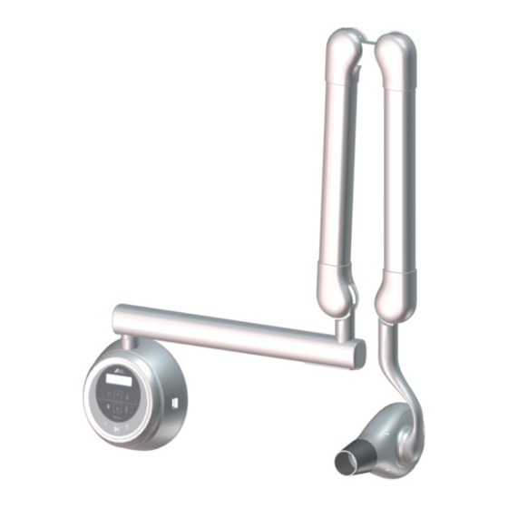
Product description Overview X-ray tube head Cone (collimator) Main power switch Control unit with control panel Handheld exposure button Horizontal Arm Scissor Arm Page 5 Air Techniques, Inc. -
Page 8: Technical Data
50 to 95 °F (+10 to +35 °C) 14 to 140 °F (-10 to +60 °C) Relative humidity 30 to 75% 10 to 75% Air pressure 25 to 31 inHg (860 to 1060 hPa) 25 to 31 inHg (860 to 1060 hPa) Page 6 Air Techniques, Inc. -
Page 9: Dimensions
(1568 mm) 35 .4 inches 68 .5 inches 73 inches 42 inches 48 inches 83 .3 inches 8 .6 inches (900 mm) (1740 mm) (1854 mm) (1068 mm) (1219 mm) (2118 mm) (220 mm) A6350-33 Page 7 Air Techniques, Inc. - Page 10 23 .6 inches (940 mm) 35 .1 inches (600 mm) (892 .5 mm) 41 inches A6350-24 (1040 mm) 50 inches 35 .4 inches (1270 mm) 48 inches (900 mm) (1219 .2 mm) 53 inches A6350-33 (1346 mm) Page 8 Air Techniques, Inc.
-
Page 11: Equipment Setup
. – Screwdriver PH1 Provecta HD unit with short extension – Screwdriver PH2 arm . . . . . . . . . . . . . . . . . . . . . . . . . . . A6350-15 –... -
Page 12: Installation Mounting Hardware
Steel wall plugs (only Bottom horizontal for concrete walls) arm cover M8x30 Screw M5x30 Screw M8x20 Screw M5x15 with spring washer Screw M3x8 Cable tie Bolt M8x25L (with 4 ea . spring & flat washers) Page 10 Air Techniques, Inc. -
Page 13: Site Preparation
Make sure the location allows sufficient space for movement of the arms in the extended condition . Make sure that the location allows the Provecta HD to be used with ease for all possible imaging procedures on the patient with respect to the patient chair location . -
Page 14: Support Load Requirements
4.7 Support Load Requirements The Provecta HD is designed to mount on either a single 4” x 4” wood stud or two 1½” x 3½” wood studs that are spaced 16-inch on center and drywall or equivalent wall support . -
Page 15: Remote Switch Configurations
Equipment Setup 4.10 Remote Switch Configurations The six remote switch configurations available for Provecta HD are shown below . Configuration No. 1 - Corded Handheld Exposure Switch and Control Keypad Handheld Console mounted to base unit . Exposure Switch (RJ11 Connector) - Page 16 2 Remote Wall Plate Pushbutton Exposure Switch Kits (A 6320) (RJ11) Power Source Control Panel or Outlet Remote Wallplate Pushbutton 3-Wire Power Exposure Switches Connection SW #1 SW #2 Control Unit with Control Panel Internal Wiring ( RJ11 Connectors) (RJ11 Connectors) Page 14 Air Techniques, Inc.
-
Page 17: Installation
5 Installation 5.1 Installation Procedure Summary This section provides procedures to install the Provecta HD . Install the Provecta HD by performing the procedures listed below and provided by the following paragraphs . 1 . X-ray base unit Wall Mounting Options... -
Page 18: Control Unit Disassembly For Base Unit Access
5.2 Control Unit Disassembly for Base Unit Access The Provecta HD control unit comprises the control panel, cover and base unit . In order access the base unit to mount on the wall plate and make connections to the associated PCB, the control unit must be disassembled . -
Page 19: Base Unit Lock Side Setup
5.3 Base Unit Lock Slide Setup The Provecta HD base unit has a lock slide that is used to control the rotation or swing of the horizontal arm . Depending on the lock slide setup, the arm can only be swung to the left 90 degrees from center, 90 degrees to the right from center or completely 180 degrees right and left . -
Page 20: Base Unit Wall Mounting Options
5.4 Base Unit Wall Mounting Options The Provecta HD base unit is designed to mount on a single wood 4 x 4 post or equivalent drywall wall stud support using either the Single Post Wall Mounting (4 x 4 inch post) Plate installation kit (P/N A6336) or the 16 Inch Center to Center Wall Mounting Plate installation kit (A6330) mounting methods . -
Page 21: Installing The Horizontal Arm
3 . Mount the horizontal arm brake with 2 screws, M5x30 . 4 . Connect the three horizontal arm cables A, B and C as shown below . Horizontal Top of Base Unit Horizontal Arm Brake Horizontal Control Panel Cable Page 19 Air Techniques, Inc. -
Page 22: Installing The Scissor Arm
7 . Connect the cables of the scissor arm and the horizontal arm and screw on the cover with the two M3x6 flat head screws . 8 . Place the horizontal arm cover on the horizontal arm . Horizontal Arm Cover Washer Ground cable H001211B Cable Connections Scissor Arm Brake Page 20 Air Techniques, Inc. - Page 23 5 . Install the supporting arm cover with the two M3x8 screws making sure not to crush the cables when installing the cover . X-ray Emitter Lock Washer Ground cable X-ray Emitter Lock Supporting Cover Cable Connections Page 21 Air Techniques, Inc.
-
Page 24: Connecting The Mains Power
Connection of the handheld exposure button to the PCB connector is made by simply inserting the as- sociated wire connector into the mating connector on the bottom of the PCB . Handheld Exposure Button Handheld Exposure Button Cable Connection RJ45 Connector RJ11 Connector Handheld Exposure Button Connector Page 22 Air Techniques, Inc. -
Page 25: Assembling The Control Unit
3 . Connect the rear keypad connector of the control panel 4 . Align the panel spine with the control unit cover center groove and slide the control panel down in place . Control Unit Connect Cover Keypad Connector Cable Control Panel Page 23 Air Techniques, Inc. -
Page 26: Scissor Arm Tension Alignment
2 . Insert the 350 mm long 5 mm allen key and turn clockwise to increase tension . 3 . Place the scissor arm straight as shown in the second image below . 4 . Insert the 350mm long 5mm allen key and turn clockwise to increase tension . Page 24 Air Techniques, Inc. -
Page 27: Connecting The Door Switch (Interlock)
. 4 . You will see the "Door Check Please . ." message on the control panel display when you try to make an exposure while the door is open . Page 25 Air Techniques, Inc. -
Page 28: Equipment Commissioning
. Set mA to '4', kVp to '60' and exposure time to '2 .0' Sec . Repeat three times . This procedure will heat the anode uniformly so that higher subsequent expo- sures will not damage it . Page 26 Air Techniques, Inc. -
Page 29: Service Menu Settings Via The Control Panel
• After entering all required values, press the button to exit the Service menu . LED Display Adult/Child selector Stand-by/Power indicator Anatomical selector X-ray emission indicator Save key Parameter adjustment key Exposure button Image plate/sensor selector Page 27 Air Techniques, Inc. -
Page 30: Warranty
Provecta HD is warranted to be free from defects in material and workmanship from the date of installation for a period of 2 years (24 months) . Provecta HD is designed solely for use in a dental office environment and this warranty is not applicable to other applications . - Page 31 For over 50 years, Air Techniques has been a leading innovator and manufac- turer of dental products. Our priority is ensuring complete satisfaction by man- ufacturing reliable products and providing excellent customer and technical support. Whether the need is digital imaging, utility room equipment or mer- chandise, Air Techniques can provide the solution via our network of authorized professional dealers.
Need help?
Do you have a question about the PROVECTA HD and is the answer not in the manual?
Questions and answers