
Related Manuals for Air Techniques AirStar Eco5 ASE121A


Summary of Contents for Air Techniques AirStar Eco5 ASE121A
- Page 1 DENTAL AIR SYSTEM ASE121A • ASE122A • ASE220A • ASE250A • ASE450A • ASE600A ASE121D • ASE122D • ASE220D • ASE250D • ASE450D • ASE600D OPERATING INSTRUCTIONS...
- Page 2 If service and maintenance work is neglected or carried out improperly, our warranty will be invalidated. Should you have any problems understanding the operating instructions please contact your local Air Techniques representative or distributor from which the unit was purchased.
-
Page 3: Table Of Contents
Appendix 2: Trouble shooting ..... . .22 Appendix 3: Spare Parts ......23 Air Techniques, Inc. Page 3... -
Page 4: Introduction And General Advice
Operator Authority: Responsible for the safe installation, regular servicing and cleaning of the product. Qualified personnel: Trained by the operating authority or by authorized Air Techniques personnel who are aware of the dangers of the product and familiar with the technical aspects of the product. -
Page 5: Product Description
The product is designed for operation in a dry, well ventilated room. Never expose the compressor station to rain. The product should not operate in a damp or wet environment. In addition, never operate the product near gases or flammable fluids. Air Techniques, Inc. Page 5... -
Page 6: Function Description Without Drying Installation (A-Units)
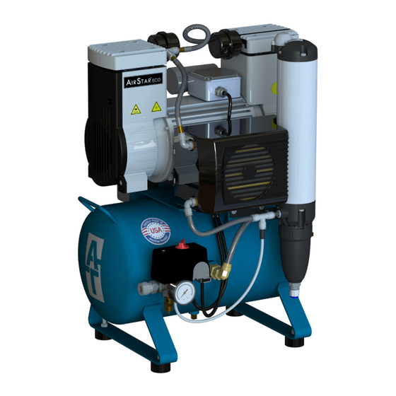
Main power / pressure switch. Compressor Pressure Gauge Damping Mount Pressure Tank Safety Relief Valve Damping Foot Pressure Switch/ Intake Filter Air Water Separator Mains Disconnect Air Outlet Pressure Hose Figure 1a. Dryer-less Compressor Key Components Page 6 Air Techniques, Inc. -
Page 7: Function Description With Drying Installation (D-Units)
(5). Excessive pressure will be released by the integrated safety relief valve (6). The tank pressure reduces when being used for procedures. On reaching the cut-in pressure the compressor aggregate will be automatically restarted by the Main power / pressure switch. Air Techniques, Inc. Page 7... - Page 8 Introduction and General Advice Compressor Pressure Gauge Intake Filter Pressure Tank Safety Relief Valve Pressure Hose Pressure Switch/ Air Cooler Damping Mount Mains Disconnect Air Outlet Membrane Dryer Damping Foot Figure 1b. Compressor with Dryer Key Components Page 8 Air Techniques, Inc.
-
Page 9: Transport, Storage, Initial Operation
Make sure that the suction sides of the air filter and the cooler are free of any obstructions. Verify that the ventilation ribs of the product are not blocked and there is sufficient space from the side wall distance. Air Techniques, Inc. Page 9... -
Page 10: Compressed Air Connection
Important: Due to harmonics and flicker data requirements, the product should be installed in a location with a maximum permissible system impedance, Zsys, of: Z = 0.109 Ohm + j 0.068 Ohm (0.109 Ohm + 216 µH). Page 10 Air Techniques, Inc. -
Page 11: Motor Protection
In the case of too high an ambient temperature, the thermal protection switch shuts down the unit by cutting off the operating current. 2.3.5 Circuit diagram The connection to the mains voltage supply must only be carried out by a qualified electrician! Air Techniques, Inc. Page 11... - Page 12 6.7/8.3 13.3/16.6 20.0/24.8 Max Wire Size (AWG) Device Breaker Rating (A) Panel Breaker Rating (A) Max Wire Size (AWG) Line Cord Length (ft) Line Cord Length (ft) Figure 2. Circuit diagram for one-phase alternating current Page 12 Air Techniques, Inc.
-
Page 13: 2.4 Electromagnetic Compatibility (Emc) Compliance Information
At 0°, 45°, 90°, 135°, 180°, 225°, 270° and 315° Voltage dips IEC 61000-4-11 0 % UT; 1 cycle and 70 % UT; 25/30 cycles Single phase: at 0° Voltage interruptions IEC 61000-4-11 0 % UT; 250/300 cycle Air Techniques, Inc. Page 13... -
Page 14: Initial Operation
• Check the cut-in pressure of the unit by releasing the pressure - 85 PSI +/- 5 PSI. Note: the cut-in and cut-out pressure may be adjusted by removing the plastic pressure switch cap and adjusting the screw within. Page 14 Air Techniques, Inc. -
Page 15: Operation
Check device breakers at back of unit. If breaker has tripped, the white reset button will be protruding. Re-depress breaker reset button. Restart the machine at the Main power / pressure switch, after the air has been blown-off of the starting volume (this will take approximately 5 seconds). Air Techniques, Inc. Page 15... -
Page 16: Maintenance
If faults occur or a repair is needed which is not dealt with in this chapter, contact Air Techniques Technical Support immediately. Warning! In the case of danger, separate the machine from the mains by placing the Main power / pressure switch to “O”... -
Page 17: Changing Suction Filters
With working pressure in the tank, turn the valve lifter (1) counterclockwise until blown off compressed air is heard. Turn the valve filter again in a clockwise direction until it is closed. Figure 5. Replace Sintered Filter Air Techniques, Inc. Page 17... -
Page 18: Repairs
Table 4-3. A-Unit Preventative Maintenance Kits ASE121A & ASE220A & AirStar ECO Model ASE450A ASE600A ASE122A ASE250A Kit Part No 84711 84712 84713 84714 C1154-1 See Table for Kit Quantities Component Part No. Compressor Air Intake Filter C1154-1 Element Page 18 Air Techniques, Inc. -
Page 19: Shutdown And Disposal
“O” - “OFF” position. Close the condensation drainage, depressurize the machine and pressure hoses. The disposal has to be carried out in an appropriate way. The national laws and stipulations have to be followed. For further questions, please contact Air Techniques. Air Techniques, Inc. Page 19... -
Page 20: Appendix 1
Since our products are subject to a process of continuous improvement, the technical spec- ification may have changed. If you propose to base your planning on these Directions for Use, please contact us beforehand for details of current data and dimensions. Page 20 Air Techniques, Inc. - Page 21 20 L 50 L 50 L 100 L Capacity Air Techniques, Inc. MEDICAL ELECTRICAL EQUIPMENT 1295 Walt Whitman Road WITH RESPECT TO ELECTRICAL SHOCK, FIRE, MECHANICAL Melville, New York, USA 11747- 3062 AND OTHER SPECIFIED HAZARDS ONLY IN ACCORDANCE WITH ANSI/AAMI ES60601-1: A1:2012, C1:2009/(R)2012 and A2:2010/(R)2012, CSA CAN/CSA-C22.2 NO.
-
Page 22: Appendix 2: Troubleshooting
Drying installation defective • Station without drying installation • Drain the condensate regularly (see par. 4.2.1) Pressure dew point is not • Purge air nozzle too small or too big • Change the purge air nozzle suitable Page 22 Air Techniques, Inc. -
Page 23: Appendix 3: Spare Parts
Appendix 3 Appendix 3: Spare Parts Figure A3-1. Parts Location for Compressor without Dryer Key Components Air Techniques, Inc. Page 23... - Page 24 Appendix 3 Figure A3-2. Parts Location for Compressor with Dryer Key Components Page 24 Air Techniques, Inc.
- Page 25 WITHOUT DRYER ASE121D: 1650100287 ASE122D: 1650100288 Air Cooler WITH DRYER All Other Units: 86752 1650100163 Membrane Dryer WITH DRYER ASE121D & ASE122D: 87266 ASE220D & ASE250D: 87267 Purge Nozzle WITH DRYER ASE450D: 87269 ASE600D: 84438 Air Techniques, Inc. Page 25...
- Page 28 For over 50 years, Air Techniques has been a leading innovator and manufacturer of dental products. Our priority is ensuring complete satisfaction by manufacturing reliable products and providing excellent customer and technical support. Whether the need is digital imaging, utility room equipment or merchandise, Air Techniques can provide the solution via our network of authorized professional dealers.
Need help?
Do you have a question about the AirStar Eco5 ASE121A and is the answer not in the manual?
Questions and answers