Samson 5824 Series Mounting And Operating Instructions
Electric actuator with positioner
Hide thumbs
Also See for 5824 Series:
- Mounting and operating instructions (92 pages) ,
- Mounting and operating instructions (64 pages) ,
- Mounting and operating instructions (20 pages)

Related Manuals for Samson 5824 Series


Summary of Contents for Samson 5824 Series
- Page 1 EB 5824-2 EN Translation of original instructions Electric Actuators Type 5824 without fail-safe action Type 5825 with fail-safe action Version with positioner Firmware version 1.04 Edition January 2015...
- Page 2 Note on these mounting and operating instructions These mounting and operating instructions assist you in mounting and operating the device safely. The instructions are binding for handling SAMSON devices. The images shown in these instructions are for illustration purposes only. The actual product may vary.
-
Page 3: Table Of Contents
Contents Safety instructions and measures ..............6 Notes on possible severe personal injury ............9 Notes on possible personal injury ..............10 Notes on possible property damage ..............10 Markings on the device ................11 Nameplate ....................11 Design and principle of operation ..............12 Fail-safe action ....................13 Cover screws ....................13 Additional functions ..................13 Device overview and operating controls ............14... - Page 4 Contents Operation ....................31 8.1 Indication with LEDs ..................31 8.1.1 Explanations to the blinking pattern of the LEDs ..........32 8.1.2 Blinking pattern of the yellow LED ..............32 8.1.3 Blinking pattern of the red LED ..............33 8.2 Direction of action switch ................34 8.3 Function switch ....................36 8.4 Initializing the actuator .................37 Configuration ....................38 Inputs and outputs ..................38 9.1.1 Input signal ....................38 9.1.2 Position feedback signal ................39 Actuator ......................39 9.2.1 Functions/actuator ..................39 9.3...
- Page 5 Contents 11.1 Emergency action ..................55 Decommissioning and removal ..............56 12.1 Decommissioning ..................56 12.2 Removing the actuator from the valve ............56 12.2.1 Force-locking attachment ................56 12.2.2 Form-fit attachment ..................56 12.3 Disposal ......................57 Annex......................57 13.1 After-sales service ..................57 13.2 Configuration list and customer-specific data ..........58 13.3 EU declarations of conformity ...............59 Firmware revisions 1.03 1.04...
-
Page 6: Safety Instructions And Measures
The actuator is designed to operate under exactly defined conditions (e.g. thrust, travel). Therefore, operators must ensure that the actuator is only used in operating conditions that meet the specifications used for sizing the actuator at the ordering stage. In case operators intend to use the actuator in other applications or conditions than specified, contact SAMSON. SAMSON does not assume any liability for damage resulting from the failure to use the de- vice for its intended purpose or for damage caused by external forces or any other external factors. Î Refer to the technical data for limits and fields of application as well as possible uses. See section 3.5. Reasonably foreseeable misuse The actuator is not suitable for the following applications: −... - Page 7 Î Observe the requirements for personal protective equipment specified in the valve docu- mentation. Î Check with the plant operator for details on further protective equipment. Revisions and other modifications Revisions, conversions or other modifications of the product are not authorized by SAMSON. They are performed at the user's own risk and may lead to safety hazards, for example. Fur- thermore, the product may no longer meet the requirements for its intended use. Safety features Upon supply voltage failure, the Type 5825 Electric Actuator causes the valve to move to a certain fail-safe position. The fail-safe action of SAMSON actuators is specified on the actua-...
- Page 8 This declaration of conformity is included in the Annex of these instructions. The Type 5824/5825 Electric Actuators are designed for use in low voltage installations. Î For wiring, maintenance and repair, observe the relevant safety regulations. Referenced documentation The following documents apply in addition to these mounting and operating instructions: − Mounting and operating instructions of the valve on which the electric actuator is mount- ed, e.g. for SAMSON valves: u EB 5861 for Type 3260 Three-way Valve u EB 5861 for Type 3260 Three-way Valve u EB 5863 for Type 3226 Three-way Valve u EB 5866 for Type 3222 Globe Valve u EB 5868 for Type 3213 and Type 3214 Globe Valves u EB 8111 for Type 3321 Globe Valve u EB 8113 for Type 3323 Three-way Valve...
-
Page 9: Notes On Possible Severe Personal Injury
Safety instructions and measures 1.1 Notes on possible severe personal injury DANGER Risk of fatal injury due to electric shock. Î Before connecting wiring, performing any work on the device or opening the device, disconnect the supply voltage and protect it against unintentional reconnection. Î Only use power interruption devices that are protected against unintentional reconnection of the power supply. -
Page 10: Notes On Possible Personal Injury
Safety instructions and measures 1.2 Notes on possible personal injury WARNING Crush hazard arising from moving parts. The form-fit version of the electric actuator contains moving parts (actuator and plug stems), which can injure hands or fingers if inserted into the actuator. Î Do not insert hands or finger into the yoke while the valve is in operation. Î Disconnect the supply voltage before performing any work on the control valve. Î Do not impede the movement of the actuator or plug stem by inserting objects into their path. -
Page 11: Markings On The Device
Markings on the device 2 Markings on the device 2.1 Nameplate SAMSON Electric Actuator Var.-ID. Model Serial no. Digital Positioner Firmware 0062 Made in Germany Type designation Year of manufacture Configuration ID Model designation (Type 5825 only) Serial number DIN registration number (Type 5825 only) Thrust Rated travel Stroking speed... -
Page 12: Design And Principle Of Operation
Design and principle of operation 3 Design and principle of oper- signal can be picked off at terminals 32 and ation The characteristic and the input and output A stepper motor allows for supply by signal settings can be changed using the frequency-independent voltages. -
Page 13: Fail-Safe Action
− The two additional limit contacts are not suitable for retrofitting. Testing according to DIN EN 14597 The Types 5825 Electric Actuator with fail- safe action "actuator stem extends" is tested by the German technical surveillance associ- ation (TÜV) according to DIN EN 14597 in combination with various SAMSON valves. Tested versions are indicated on the name- plate. They are listed in the Technical data table. The registration number is available on re- quest. EB 5824-2 EN... -
Page 14: Device Overview And Operating Controls
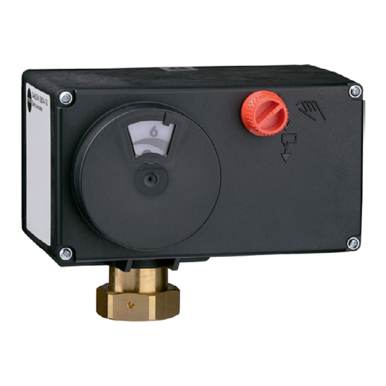
Design and principle of operation 3.4 Device overview and operating controls Travel indication scale Handwheel (Type 5824 only) Fig. 2: Location of external operating elements 3.4.1 Type 5824 (24 V version) Actuating shaft Serial interface Direction of action switch Red and yellow LEDs Function switch Fig. 3: Location of operator controls under the front cover of Type 5824 (24 V version) EB 5824-2 EN... -
Page 15: Type 5824, 85 To 264 V Version
Design and principle of operation 3.4.2 Type 5824 (85 to 264 V version) Actuating shaft Serial interface Direction of action switch Red and yellow LEDs Function switch Fig. 4: Location of operator controls under the front cover of Type 5824 (85 to 264 V version) EB 5824-2 EN... -
Page 16: Technical Data
Design and principle of operation 3.5 Technical data Table 1: Technical data · Type 5824 Type 5824 Fail-safe action Without Rated travel Stroking speed Slow mm/s 2), 3) 0.13 0.13 0.13 Standard mm/s Fast mm/s 0.36 0.36 0.36 Transit time for rated Slow travel Standard... - Page 17 Design and principle of operation Type 5824 Safety Degree of protection IP 54 Class of protection II according to EN 61140 Overvoltage category II according to EN 60664 Degree of contamination 2 according to EN 60664 Noise immunity According to EN 61000-6-2 Noise emission According to EN 61000-6-3 Vibration According to EN 60068-2-6 and EN 60068-2-27 · Conformity Additional electrical equipment (not suitable for retrofitting) Two limit contacts , max. 230 V, 1 A •...
- Page 18 Design and principle of operation Table 2: Technical data · Type 5825 Type 5825 Fail-safe action Extends Retracts Rated travel Stroking speed Slow mm/s 2), 3) 0.13 0.13 0.13 0.13 0.13 0.13 Standard mm/s Fast mm/s 0.36 0.36 0.36 0.36 0.36 0.36 Transit time for rated Slow...
- Page 19 Design and principle of operation Type 5825 Safety Degree of protection IP 54 Class of protection II according to EN 61140 Overvoltage category II according to EN 60664 Degree of contamination 2 according to EN 60664 Noise immunity According to EN 61000-6-2 Noise emission According to EN 61000-6-3 Vibration According to EN 60068-2-6 and EN 60068-2-27 Conformity Testing according to DIN EN 14597 – – – – Additional electrical equipment (not suitable for retrofitting) Two limit contacts , max. 230 V, 1 A •...
-
Page 20: Accessories
Design and principle of operation 3.6 Accessories Table 3: Accessories Accessories for version with digital positioner (see Order number Fig. 17 on page 54) Hardware package consisting of: 1400-9998 − Memory pen-64 − Connecting cable − Modular adapter Memory pen-64 1400-9753 Connecting cable 1400-7699 Modular adapter 1400-7698 USB to RS-232 adapter 8812-2001 Software TROVIS-VIEW (free of charge) u www.samsongroup.com > Service & Support > Downloads > TROVIS-VIEW... -
Page 21: Dimensions In Mm
Design and principle of operation 3.7 Dimensions in mm Types 5824-10/-20 and Types 5825-10/-20/-15/-25 Type 5824-30 and Types 5825-30/-35 Actuator without yoke Actuator with yoke (1400-7414) 15 mm 15 mm travel travel Ø 10 Fig. 5: Dimensions EB 5824-2 EN... -
Page 22: Measures For Preparation
− Observe the storage instructions. 4.1 Unpacking − Avoid long storage times. − Contact SAMSON in case of different stor- age conditions or long storage periods. Note Do not remove the packaging until immedi- ately before mounting and start-up. -
Page 23: Aligning The Travel Indication Scale
Measures for preparation 4.4 Aligning the travel indica- Hole for driving pin tion scale with three-way mixing valve The travel indication scale has two opposed scales. Which scale is to be used depends on the valve version (Fig. 6). In the delivered state, the scale alignment applies to globe valves and three-way diverting valves. The alignment needs to be changed when a three-way mixing valve is used (see below). -
Page 24: Mounting And Start-Up
Mounting and start-up 5 Mounting and start-up 5.1.2 Type 5824: form-fit attachment NOTICE 1. Place the actuator on the yoke and tight- Risk of malfunction due to incorrectly per- en coupling nut (4) (tightening torque formed start-up. 20 Nm). Perform start-up following the described se- 2. - Page 25 Mounting and start-up Handwheel Actuator stem with actuator piston Coupling nut 15 Yoke 16 Stem connector 17 Nut Force-locking attachment with coupling nut, e.g. Form-fit attachment with stem connector, e.g. with to Type 3222 Valve yoke on Series V2001 Valve Fig. 7: Attaching actuator and valve Actuating shaft Tag at final travel value (torque-dependent limit switch activated) Fig. 8: Tag EB 5824-2 EN...
-
Page 26: Type 5825: Form-Fit Attachment
Mounting and start-up 5.1.4 Type 5825: form-fit NOTICE attachment Risk of damage to the actuator by turning it too far. Î For fail-safe action “actuator stem re- Only retract the actuator stem as far as the tracts” and “actuator stem extends”, final travel value. mount actuator as described in sec- tion 5.1.2. -
Page 27: Electrical Connection
Mounting and start-up Note NOTICE The degree of protection IP 54 can only be Movement of the actuator stem will disturb achieved up to device index .03 when the the process. actuator is installed in the upright position. After connecting the supply voltage, the ac- See the last two figures of the configuration tuator moves through part of its travel range. - Page 28 Mounting and start-up Depending Input on version 0...10 V 85...264 V AC Output 0...20 mA 24 V AC, 24 V DC _ /~ +/~ 0...10 V Limit contacts as additional function (in 24 V version only) 41 44 42 51 54 Fig. 10: Electrical connection Note The 24 V version can be used either with a supply voltage of 24 V AC or 24 V DC. EB 5824-2 EN...
-
Page 29: Additional Functions
Additional functions 6 Additional functions Devices in 24 V version can be fitted with limit contacts as additional function. The limit contacts (6 in Fig. 1 on page 12) can be used either as make or break con- tacts. 6.1 Adjusting the limit contacts DANGER Risk of electric shock from exposed live parts. Do not touch live parts on adjusting the limit contacts. -
Page 30: Handwheel
Handwheel 7 Handwheel 7.1 Manual override of Type 5825 Actuator The handwheel is used to move the actuator stem manually (approx. 4 turns for 1 mm) when the supply voltage is disconnected. DANGER Direction of action and actuator travel can Risk of electric shock from exposed live be read off the travel indicator scale parts. -
Page 31: Operation
Operation 8 Operation 8.1 Indication with LEDs The actuator has a red and a yellow LED which indicate the operating state of the actuator through a blinking pattern. The LEDs are located underneath the cover on top of the actuator. LEDs under the front cover of Type 5824 (24 V version) LEDs (red and yellow) -
Page 32: Explanations To The Blinking Pattern Of The Leds
Operation 8.1.1 Explanations to the blinking pattern of the LEDs Gray: LED illuminated White: LED not illuminated The state of the corresponding LED (on/off) is shown over time. Time [s] Time [s] 8.1.2 Blinking pattern of the yellow LED Device ON, communication ready: Time [s] Stem position is relative: Time [s] Blocking protection active (see section 9.3.1): Time [s] Note... -
Page 33: Blinking Pattern Of The Red Led
Operation 8.1.3 Blinking pattern of the red LED Restarting device after reset or torque-dependent limit switch error: Time [s] Input signal failure recognized (see section 9.2.1): Time [s] EEPROM error: Time [s] Zero calibration in progress (see section 9.6.3): Time [s] Transit time measurement in progress: Time [s] Initialization in progress (see section 8.4): Time [s] EB 5824-2 EN... -
Page 34: Direction Of Action Switch
Operation 8.2 Direction of action switch The position of the direction of action switch determines the actuator's direction of action. − Switch position A (default): direction of action increasing/increasing (>>) Î The actuator stem retracts as the input signal increases. − Switch position B: direction of action increasing/decreasing (<>) Î The actuator stem extends as the input signal increases. Direction of action switch in Type 5824 (24 V version) Direction of action switch with switch positions: Direction of action switch in Type 5824 (85 to 264 V version) - Page 35 Operation Actuator stem extended − For globe valves: Valve closed − For three-way mixing valves: Port A à AB open, B à AB closed − For three-way diverting valves: Port AB à A closed, AB à B open Actuator stem retracted − For globe valves: Valve open − For three-way mixing valves: Port A à AB closed, B à AB open − For three-way diverting valves: Port AB à A open, AB à B closed Mixing valve for mixing service For diverting service Flow pipe Flow pipe Return flow pipe Return flow pipe Diverting valve for mixing service For diverting service...
-
Page 36: Function Switch
Operation 8.3 Function switch The function switch has the following functions: 1. Determining the input signal range 2. Start initialization (see section 8.4) − Switch position A (default): Î Input signal 0 to 10 V or 0 to 20 mA Î Input signal settings in TROVIS-VIEW are taken into account. − Switch position B: Î Input signal 2 to 10 V or 4 to 20 mA Î Input signal settings in TROVIS-VIEW are ignored. Function switch in Type 5824 (24 V version) Function switch with switch positions: Function switch in Type 5824 (85 to 264 V version) -
Page 37: Initializing The Actuator
Operation 8.4 Initializing the actuator To achieve correct position feedback, the actuator must be initialized. This is also necessary after changing any settings at the actuator. WARNING Risk of injury due to the actuator stem extending or retracting. Do not touch or block the actuator stem. NOTICE Movement of the actuator stem will disturb the process. Do not perform the initialization while the process is running. -
Page 38: Configuration
Configuration 9 Configuration The actuator is configured with the TROVIS-VIEW software. In this case, the serial interface on the actuator is used to connect the actuator to the computer. Î Refer to u EB 6661 for more details on configuration and operation using TROVIS- VIEW. 9.1 Inputs and outputs 9.1.1 Input signal The input signal determines the actuator stem position. A voltage or current signal can be used as the input signal. -
Page 39: Position Feedback Signal
Configuration 9.1.2 Position feedback signal The position feedback indicates the position of the actuator stem. The span of the position feedback signal is adjusted over the lower and upper range value parameters. Set position feedback signal: Settings\Inputs and outputs\Position feedback signal Position feedback signal Adjustment range Lower range value 0.0 V... - Page 40 Configuration − Positioning value upon input signal failure = Last position The actuator stem remains in the last position that the valve moved to before failure of the input signal. The error message is cleared and the actuator returns to closed-loop operation if the input signal moves within 0.2 V or 0.4 mA of the lower range value.
-
Page 41: Blockage
Configuration 9.3 Blockage 9.3.1 Blocking protection The blocking protection prevents the valve from seizing up. If the actuator stem is in the closed position (0 %), it is extended slightly and then moved back to the closed position 24 hours after it last moved. Movement of the actuator stem caused by the activated blocking protection is indicated by the yellow LED: Time [s] Blocking protection settings: Settings\Actuator\Blockage Function Adjustment range Blocking protection Yes/No 9.4 Travel 9.4.1 Limited travel range The Limited travel range parameter determines in % how far the actuator stem can move at... -
Page 42: Idle Time During End Position Guiding
Configuration − Absolute travel adjustment: The absolute travel adjustment causes the actuator stem to move to the travel position de- termined by the input signal. To achieve this, an automatic zero calibration is performed after every start-up to obtain a reference value for the zero point. The position feedback indicates the position of the actuator stem. − Relative travel adjustment The relative travel adjustment causes the change in input signal to be reproduced by the position of the actuator stem. The actuator stem extends or retracts from the current travel position corresponding to the change in signal. After starting up the actuator, a zero cali- bration is not performed. -
Page 43: Characteristic
Configuration Stroking speed The actuator stem moves to the position determined by the input signal at the selected strok- ing speed. There are three speed levels: − Slow = 0.135 mm/s − Standard = 0.197 mm/s − Fast = 0.365 mm/s Speed settings: Settings\Actuator\Travel Function Adjustment range Velocity Standard Slow, Standard, Fast Note The transit time is calculated from the travel and the stroking speed. The transit time is the time that the actuator stem needs to move through the adjusted travel. - Page 44 Configuration Characteristic types − Linear Y in % The travel is proportional to the input signal. X in % Input signal Y in % − Equal percentage The travel is exponential to the input signal. X in % Input signal Y in % − Reverse equal percentage The travel is reverse exponential to the input signal. X in % Input signal − User-defined A new characteristic based on the characteristic set can be defined over eleven points. EB 5824-2 EN...
-
Page 45: Operating Values
Configuration 9.5 Operating values Note The values in the Operating values folder cannot be changed. In online mode, the current operating values are listed in the Operating values folder. De- pending on the basic setting, operating values are plotted in a graph underneath. 9.6 Service The Service folder is subdivided into the areas Start-up, Operating states, Functions, Status messages and Statistics. - Page 46 Configuration − Retract actuator stem − Extend actuator stem − Move stem to standardized positioning value First enter the required positioning value in relation to the input signal range (standard- ized positioning value). − Issue a standardized position feedback First enter the required position feedback in relation to the span of the position feedback signal (standardized position feedback).
-
Page 47: Status Messages
Configuration 9.6.4 Status messages In the Service folder (Status messages), device and operation parameters are shown. Device Firmware version Serial number Device information Manufacturing parameters Operation Operating hours in h Operating hours at excess temperature in h Temperature inside device in °C Highest temperature inside device in °C Lowest temperature inside device in °C Actuator strokes Motor transit time... -
Page 48: Statistics
Configuration 9.6.5 Statistics In the Service folder (Statistics), various readings of counters are shown. Device failures counters Supply voltage activated Program interruptions Limit contact error EPROM error Alarms counters Input signal failures Counter: switch Direction of action switch Function switch Initialization Counter: manual overrides Manual overrides Memory pen counters... -
Page 49: Memory Pen
Configuration 9.7 Memory pen u EB 6661 The memory pen can be loaded with data configured in TROVIS-VIEW and the configuration data transferred to one or several devices of the same type and version. Additionally, the data from the device can be written to the memory pen. This allows the con- figuration data to be simply copied from one device and loaded onto other devices of the same type and version. The data logging function also allows operating data to be recorded. - Page 50 Configuration Preparing data logging: Time [s] Data logging in progress: Time [s] Plausibility error in memory pen: Time [s] EEPROM error in memory pen: Time [s] EB 5824-2 EN...
-
Page 51: Data Transmission Between The Actuator And Memory Pen
Configuration 9.7.2 Data transmission between the actuator and memory pen The memory pen is connected to the actuator as shown in Fig. 16. Refer to the TROVIS-VIEW Operating Instructions u EB 6661 on how to transfer data. Memory pen Serial interface (RJ12 jack) Fig. 16: Connecting actuator and memory pen The yellow LED on the actuator indicates that the data logging is being prepared. Data transmission is completed when the yellow LED is illuminated continuously (see sec- tion 8.1.2). -
Page 52: Copying Function
Configuration 9.7.3 Copying function The memory pen can be used to copy setting data to other Types 5824 and 5825 Actuators after the data from the actuator have been transferred to the memory pen. Note “Automatically write to memory pen” is automatically reset to the read status after data are transferred from the actuator for the first time. 9.7.4 Data logging The memory pen-64 allows the following data to be saved:... -
Page 53: Command Mode
2. Select Read Logged Data from the Memory Pen menu. 3. Select the desired target directory. If the target directory is not changed, data will be saved in the SAMSON folder > Type 5824. 4. Enter the file name. 5. Click Save to start data transmission. -
Page 54: Servicing
Servicing 10 Servicing Note RS232 The electric actuator was checked by SAMSON before it left the factory. Adapter: order no. 8812-2001 − The product warranty becomes void if service or repair work not described in these instructions is performed without prior agreement by SAMSON's after-sales... -
Page 55: Malfunctions
Malfunctions 11 Malfunctions Î Troubleshooting (see Table 4). Note Contact SAMSON's After-sales Service for malfunctions not listed in the table. Table 4: Troubleshooting Error Possible reasons Recommended action Actuator stem does not move. Actuator is blocked. Î Check attachment. Î Remove the blockage. No or incorrect supply voltage Î... -
Page 56: Decommissioning And Removal
Decommissioning and removal 12 Decommissioning and 2. Completely drain the pipelines and valve. removal 3. Disconnect the supply voltage and pro- tect it against unintentional reconnection. DANGER DANGER 4. If necessary, allow the pipeline and valve Risk of fatal injury due to electric shock. components to cool down. -
Page 57: Disposal
Î Do not dispose of components, lubricants Addresses of SAMSON AG and its subsid- and hazardous substances together with iaries your other household waste. The addresses of SAMSON, its subsidiaries, representatives and service facilities worldwide can be found on our website On request, we can appoint a service pro- (u www.samsongroup.com) or in all vider to dismantle and recycle the product. -
Page 58: Configuration List And Customer-Specific Data
Annex 13.2 Configuration list and customer-specific data Performed Configuration Default setting Adjustment range setting Input signal 0.0 V 0.0 to 7.5 V Lower range value 0.0 mA 0.0 to 15.0 mA 10.0 V 2.5 to 10.0 V Upper range value 20.0 mA 5.0 to 20.0 mA Unit V/mA Position feedback signal Lower range value 0.0 V 0.0 to 10.0 V Upper range value 10.0 V 0.0 to 10.0 V Functions Detect input signal failure... -
Page 59: Eu Declarations Of Conformity
LVD 2014/35/EU EN 60730-1:2016, EN 61010-1:2010 RoHS 2011/65/EU EN 50581:2012 Hersteller / Manufacturer / Fabricant: SAMSON AKTIENGESELLSCHAFT Weismüllerstraße 3 D-60314 Frankfurt am Main Deutschland/Germany/Allemagne Frankfurt / Francfort, 2017-07-29 Im Namen des Herstellers/ On behalf of the Manufacturer/ Au nom du fabricant. - Page 60 +A1:2011 LVD 2014/35/EU EN 60335-1:2012 RoHS 2011/65/EU EN 50581:2012 Hersteller / Manufacturer / Fabricant: SAMSON AKTIENGESELLSCHAFT Weismüllerstraße 3 D-60314 Frankfurt am Main Deutschland/Germany/Allemagne Frankfurt / Francfort, 2017-07-29 Im Namen des Herstellers/ On behalf of the Manufacturer/ Au nom du fabricant.
- Page 62 EB 5824-2 EN...
- Page 63 EB 5824-2 EN...
- Page 64 EB 5824-2 EN SAMSON AKTIENGESELLSCHAFT Weismüllerstraße 3 · 60314 Frankfurt am Main, Germany Phone: +49 69 4009-0 · Fax: +49 69 4009-1507 samson@samsongroup.com · www.samsongroup.com...
Need help?
Do you have a question about the 5824 Series and is the answer not in the manual?
Questions and answers