Advertisement
Quick Links
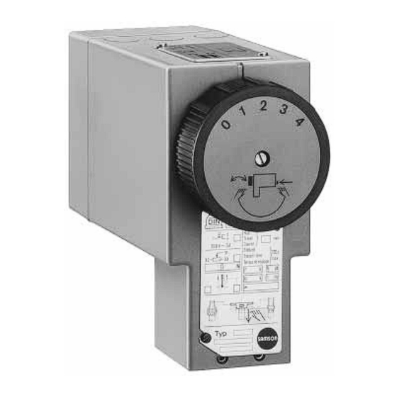
Electric Actuators
Type 5821 ⋅ Type 5822, form-fit connection
Type 5821 ⋅ Type 5822, force-locking connection
Type 5821 Electric Actuator,
form-fit connection
Fig. 1 ⋅ Electric actuators
1. Design and principle of operation
The electric actuators basically consist of a re-
versable synchronous motor of the perma-
nent-magnet rotor type with a maintenance-
free gear. The actuator components housed in
the plastic enclosure are connected to the
control valves using one of two methods: 1)
form-fit by means of two connecting clamps
and a clamp ring or 2) force-locking by
means of a union nut.
Edition September 1993
Type 5822 Electric Actuator,
force-locking connection
Actuators with fail-safe action (Type 5822
Actuator) are equipped with a spring mech-
anism which, depending on the operating di-
rection, opens or closes the connected valve.
Typetest
The actuators with fail-safe action OUT "actu-
ator stem extends" have been tested acc. to
DIN (DIN 32 730) in combination with
various control valves. The respective register
numbers are printed on the nameplate.
Mounting and operating instructions
EB 5821/5822 E
Advertisement

Related Manuals for Samson 5821


Summary of Contents for Samson 5821
- Page 1 Electric Actuators Type 5821 ⋅ Type 5822, form-fit connection Type 5821 ⋅ Type 5822, force-locking connection Type 5821 Electric Actuator, Type 5822 Electric Actuator, form-fit connection force-locking connection Fig. 1 ⋅ Electric actuators 1. Design and principle of operation Actuators with fail-safe action (Type 5822...
- Page 2 The Type 5822-30 Actuator and Type 5822- via two limit switches. 31 Actuator require an external active spring Type 5821 Actuator (Figs. 2 and 3) force of 140 N across the entire travel in In these versions, the motor of the actuator is operating direction IN "actuator stem re-...
- Page 3 12.1 Fig. 3 ⋅ Type 5821-5, -6 Fig. 2 ⋅ Type 5821-1, -2, -3 form-fit connection force-locking connection 12.1 Fig. 4 ⋅ Type 5822-10, -20, -30, -40 operating Fig. 5 ⋅ Type 5822-50, -60, -70 direction OUT (Type 5822-11, -21, -31, -41...
- Page 4 1.3 Additional electrical equipment 2.1 Attaching the adapter (connecting parts) The actuators can optionally be equipped with two overrangeable limit switches and/or 2.1.1 Series 240 Control Valves (up to nomi- a potentiometer. nal size DN 25) Limit switches Follow the assembly steps listed below: The limit switches are actuated by two cam 1.
-
Page 5: Form-Fit Connection
Force-locking connection Form-fit connection Direct connection on valve Direct connection or insulating section on valve Connecting parts Connecting parts 1070-6837 1070-6838 Adapter 6.1 Coupling nut Ring nut 6.2 Lock nut Adapter rod Bonnet Coupling clamps Travel indicator 10 Threaded pin Plug stem Fig. - Page 6 4. Slide the clamp ring (6.2) downwards in Type 5821 Actuator Follow the assembly steps listed below: the direction of the control valve until it stops, causing the connecting clamps to 1. Unscrew the nameplate (1.4) on the actua- close and lock into position. The clamp tor.
- Page 7 Clamp ring Clamp ring upwards - Clamp ring downwards - (unlocked) (locked) Fig. 7 ⋅ Clamp ring Control signal Controller PE 24 V~** 24 V~** Limit switch Operating direction OUT IN L N L N 12 11 13 Control signal 12 11 14 22 21 24 Potentiometer PE N...
- Page 8 4.1 Manual operation of the actuator the position indicator of the controller as indi- (Type 5821 only) cated in the wiring diagram (Fig. 8). Move If the release button (2) is actuated, the clutch...
- Page 9 Adjuster Presetting: The adjusters for adapting the reference vari- Adjust the connector for direct operating di- able (input signal) and travel range are lo- rection >>, since the actuator stem must re- cated under the cover plate on the top side of tract with increasing current input so that the valve can be opened.
- Page 10 Depending on the runtime of the motor, the actuator stem and the plug stem retract in the upper end position. Note the plug stem on the travel indicator. When the desired travel po- sition has been reached, turn span adjuster slowly counter-clockwise until the LED just begins to disilluminate.
- Page 11 5. Dimensions in mm Only for Type 5821 Actuator Form-fit connection Only for Force-locking connection Type 5821 Actuator SW 36 M32x1.5...
- Page 12 SAMSON AG ⋅ MESS- UND REGELTECHNIK Weismüllerstraße 3 ⋅ D-60314 Frankfurt am Main Postfach 10 19 01 ⋅ D-60019 Frankfurt am Main EB 5821/5822 E Telefon (0 69) 4 00 90 ⋅ Telefax (0 69) 4 00 95 07...
Need help?
Do you have a question about the 5821 and is the answer not in the manual?
Questions and answers