
Related Manuals for Samson 2488 N


Summary of Contents for Samson 2488 N
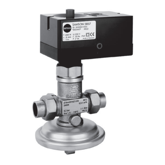
- Page 1 Pressure-independent Control Valve (PICV) Type 2488 N/5857 Type 2488 N/5857 Mounting and Operating Instructions EB 3136 EN Edition December 2017...
- Page 2 Î For the safe and proper use of these instructions, read them carefully and keep them for later reference. Î If you have any questions about these instructions, contact SAMSON‘s After-sales Service Department (aftersalesservice@samson.de). The mounting and operating instructions for the devices are included in the scope of delivery.
-
Page 3: Table Of Contents
Contents Safety instructions and measures ..............4 Notes on possible severe personal injury ............6 Notes on possible personal injury ..............7 Notes on possible property damage ..............7 Markings on the device .................8 Nameplate for Type 2488 N Valve ..............8 Design and principle of operation ..............9 Technical data .....................10 Measures for preparation ................14 Unpacking ....................14... -
Page 4: Safety Instructions And Measures
SAMSON. SAMSON does not assume any liability for damage resulting from the failure to use the de- vice for its intended purpose or for damage caused by external forces or any other external factors. - Page 5 Revisions, conversions or other modifications of the product are not authorized by SAMSON. They are performed at the user's own risk and may lead to safety hazards, for example. Furthermore, the product may no longer meet the requirements for its intended use.
-
Page 6: Notes On Possible Severe Personal Injury
Safety instructions and measures Referenced standards and regulations The regulators comply with the requirements of the European Pressure Equipment Directive 2014/68/EU. Devices with a CE marking have an EU declaration of conformity, which in- cludes information about the applied conformity assessment procedure. This EU declaration of conformity is included in the Appendix of these instructions (see section 9.2). -
Page 7: Notes On Possible Personal Injury
Safety instructions and measures 1.2 Notes on possible personal injury WARNING Risk of personal injury due to residual process medium in the valve. While working on the valve, residual process medium can escape and, depending on its properties, may lead to personal injury, e.g. (chemical) burns. Î... -
Page 8: Markings On The Device
6 Max. perm. differential pressure Δp in bar 7 Flow coefficient K 8 Max. permissible temperature in °C 9 Nominal pressure PN Three-step version SAMSON 5857 Electric Actuator Nameplate of Type 5857 Actuator Configuration ID F: 3 Serial number Thrust Var.-ID... -
Page 9: Design And Principle Of Operation
Design and principle of operation 3 Design and principle of oper- leased by the valve plug (3) and the adjust- able restriction (11). ation The installed positioning spring (5) deter- Î Refer to Fig. 2 mines the differential pressure across the re- The pressure-independent control valve striction of 0.2 bar. -
Page 10: Technical Data
Noise emission control of water and non-flammable gases. − Non-flammable gases up to 80 °C SAMSON is unable to make general state- ments about noise emission as it depends on − Liquids up to 110 °C the valve version, plant facilities and process The regulator is open when relieved of pres- medium. - Page 11 Design and principle of operation Table 1: Technical data for Type 2488 N Valve Type 2488 N Valve Valve size DN 15 Nominal pressure PN 10 Max. perm. differential pressure Δp 4 bar coefficient Standard version Special version Max. permissible temperature Treated water 110 °C Non-flammable gases 80 °C Flow rate set point range/limitation for water with a differential pressure at the restriction of 0.2 bar...
- Page 12 Design and principle of operation Table 2: Technical data of Type 5857 Actuator Type 5857 Actuator Three-step With digital positioner Version Connection to valve Force-locking Rated travel 6 mm Transit time for rated travel 20 s 30/20 /10 s Thrust 300 N 230 V (±10 %), 50 Hz 24 V (±10 %), 50 Hz, Power supply 24 V (±10 %), 50 Hz 60 Hz and DC...
- Page 13 Design and principle of operation Ø12 ISO 228/1-G ¾ B Intermediate insulating Ø95 piece SW30 SW30 Welding ends Threaded ends Fig. 3: Dimensional drawings EB 3136 EN...
-
Page 14: Measures For Preparation
− Observe storage instructions. note. − Avoid long storage times. 2. Check the shipment for transportation − Contact SAMSON in case of different stor- damage. Report any damage to age conditions or long storage periods. SAMSON and the forwarding agent (refer to delivery note). - Page 15 Î Check the valve to make sure it is clean. Î Check the valve and actuator to make sure they are not damaged. SAMSON's After-sales Service department Î Check to make sure that the type desig- can provide more detailed storage instruc- nation, valve size, material, pressure rat- tions on request.
-
Page 16: Preparation For Installation
For example, the SAMSON Type 1 NI Strainer is suitable − The electric actuator must be mounted (u T 1010). above the valve body. -
Page 17: Mounting The Actuator
Mounting and start-up 5.3 Mounting the actuator Î Refer to Fig. 2 Î Place the actuator (16) on the valve con- nection and hand-tighten the coupling nut (17). Type 2488 N/5825 Indirect connection to district heating system with Type 2488 N/5825 PICV Fig. 4: Sample application EB 3136 EN... -
Page 18: Electrical Connection
Mounting and start-up 5.4 Electrical connection Three-step version Î See Fig. 5 and Fig. 2 24 V, 50 H WARNING Upon installation of the electric cables, you are required to observe the regulations con- cerning power installations according to DIN VDE 0100 as well as the regulations of your local power supplier. -
Page 19: Start-Up
Mounting and start-up 5.5 Start-up Rinsing the plant 1. After filling the plant, first completely Î First start up the regulator after mounting open the consumer all parts. 2. Adjust the maximum flow rate at the reg- Î Make sure that the restriction (11) is ulator (see section 6.1.1). -
Page 20: Operation
Operation 6 Operation 6. Guide the wire through the lead-seal hole and lead-seal it to fix the adjusted 6.1 Adjusting the set point flow rate. 7. Reconnect the power supply to the elec- 6.1.1 Flow rate tric actuator (16). Î Completely open the control and shut-off valves or the bypass valve in the plant. -
Page 21: Servicing
WARNING Risk of burn injuries due to hot or cold com- ponents and pipelines. SAMSON's After-sales Service department Depending on the process medium, valve can support you in drawing up an inspection components and pipelines may get very hot and test plan for your plant. -
Page 22: Preparation For Return Shipment
Malfunctions 7.2 Ordering spare parts and Note operating supplies The regulator was checked by SAMSON be- fore it left the factory. Contact your nearest SAMSON subsidiary − The product warranty becomes void if ser- or the SAMSON After-sales Service depart-... -
Page 23: Malfunctions
Control loop hunts. Valve too large for control task SAMSON for further action. Note Contact SAMSON's After-sales Service department for malfunctions not listed in the table and when the malfunction cannot be remedied as described. EB 3136 EN... -
Page 24: Decommissioning
To decommission the regulator for service partment at aftersalesservice@samson.de. and repair work or disassembly, proceed as follows: Addresses of SAMSON AG and its subsid- iaries 1. Close the shut-off valve on the upstream side of the valve. The addresses of SAMSON AG, its subsidiaries, representatives and service 2. - Page 25 Appendix Modul H/Module H, Nr./No. / N° CE-0062-PED-H-SAM 001-16-DEU-rev-A SAMSON erklärt in alleiniger Verantwortung für folgende Produkte:/For the following products, SAMSON hereby declares under its sole responsibility: Ventile für Druck- Differenzdruck-, Volumenstrom- und Temperaturregler/Valves for pressure, differential pressure, volume flow and temperature regulators 2333 (Erz.-Nr./Model No.
- Page 26 Appendix Modul H/Module H, Nr./No. / N° CE-PED-H-SAM 001-13-DEU-rev-A SAMSON erklärt in alleiniger Verantwortung für folgende Produkte:/For the following products, SAMSON hereby declares under its sole responsibility: Ventile für Druck-, Differenzdruck-, Temperatur- und Volumenstromregler/Valves for pressure, temperature, flowregulators and differential pressure regulators Typ 2336, 2373, 2375, 44-1B, 44-2, 44-3, 44-4, 44-6B, 44-9, 45-1, 45-2, 45-3, 45-4, 45-6, (Erz.-Nr.
- Page 27 EB 3136 EN...
-
Page 28: Eb 3136 En
SAMSON AG · MESS- UND REGELTECHNIK Weismüllerstraße 3 · 60314 Frankfurt am Main, Germany Phone: +49 69 4009-0 · Fax: +49 69 4009-1507 EB 3136 EN samson@samson.de · www.samson.de...
Need help?
Do you have a question about the 2488 N and is the answer not in the manual?
Questions and answers