Table of Contents
Advertisement
Quick Links
INSTRUCTION MANUAL
PARECT
Electro - pneumatic Regulator
MEVT Series
COMMON TERMINAL STAND
TYPE
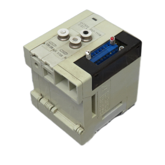
MEVT - T11R
D-SUB CONNECTOR TYPE
MEVT - T30R
Please
read
●
carefully before using this product, par-
ticularly the section describing safety .
Retain this instruction manual with the
●
product for further consultation whenev-
er necessary .
SM−295321−A
this
instruction
Ver.4
manual
Advertisement
Table of Contents

Related Manuals for CKD PARECT MEVT Series


Summary of Contents for CKD PARECT MEVT Series
- Page 1 SM−295321−A INSTRUCTION MANUAL PARECT Electro - pneumatic Regulator MEVT Series COMMON TERMINAL STAND TYPE MEVT - T11R D-SUB CONNECTOR TYPE MEVT - T30R Please read this instruction manual ● carefully before using this product, par- ticularly the section describing safety . Retain this instruction manual with the ●...
- Page 2 For Safety Use To use this product safety, basic knowledge of pneumatic equipment, including materials, piping, electrical system and mechanism, is required (ISO 4414 *1 JIS B 8370 *2). We do not bear any responsibility for accidents caused by any person without such knowledge or arising from im- proper operation.
- Page 3 CAUTION Points to caution when handling the product (1) Inferior quality air will deteriorate the product characteristics and affect its durability badly. Use an air dryer, filter and Oil mist filter to eliminate solid material, moisture and tar and thus provide clean air from the pressure source.
- Page 4 (8) Avoid operating the product in places where it may be affected by direct sunlight, water or oil. (9) If the product remains connected to its supply pressure for a long time while leaving the power turned off, the output pressure may increase to the level of the supply pressure.
- Page 5 INDEX MEVT Series PARECT Electro-pneumatic Regulator COMMONTERMINAL STAND TYPE (MEVT-T11R) D-SUB CONNECTOR TYPE (MEVT-T30R) Manual No. SM-295321-A 1. DESIGN AND SELECTION 2. INSTALLATION 3. OPERATION 4. MAINTENANCE 5. PRODUCTS 5.1 Specifications 5.2 Dimensions Inside structure Component Block constitution 6. WIRING Common Terminal Stand Type (T11R) D-sub Connector Type (T30R) 7.
-
Page 6: Design And Selection
1 DESIGN AND SELECTION 1. DESIGN AND SELECTION (1) With a thorough understanding of compressed air ! WARNING : characteristics, design a pneumatic circuit. Where instantaneous stop holding at emergency stop is required, the same function as in the mechanical or hy- draulic or electrical units cannot be expected. There arise pop-up, jet-out and leaking phenomena caused by compressibility and expansibility, which are air characteristics. (2) Prior to use, always ensure that the product with- stands the operating environment. - Page 7 1 DESIGN AND SELECTION (1) Note the maintenance conditions clearly in the ! CAUTION : equipment instruction manual. The product functions may significantly lower, depending on the operating condition, operating environment and maintenance situation, thereby safety might not be se- cured. If this maintenance work is conducted accurately and correctly, it is possible to exhibit the product func- tion and performance sufficiently. (2) Use be a constant voltage power supply. (3) Check the leak current to avoid a malfunction caused ...
- Page 8 1 DESIGN AND SELECTION Avoid using a product in blowing or under the operating ! CAUTION : conditions that the back pressure is applied to the sec- ondary side. No set pressure can be maintained, and its service life may be shortened along with a large beat sound. (7) EVT100 arises residual pressure of 2kPa max and EVT500, ...
-
Page 9: Installation
2 INSTALLATION 2. INSTALLATION (1) For MEVT installation, do not use the method of ! WARNING : supporting the MEVT with piping. Attach and fix the MEVT main body. (2) Do not wash and coat the MEVT, using water and solvent . Some plastics parts may be damaged. The coating agent may block the exhaust port, causing malfunctions. -
Page 10: When Installing
2 INSTALLATION When installing: ! CAUTION : (1) Keep a sufficient space for removal & re-installation, wiring and piping work around the EVT. (2) Provide a pneumatic filter just in the pre-stage of the circuit in which the pneumatic equipment is used. (3) The response time is af- fected by operating pressure and load ca- pacity. When stable reproduci- bility is required for this responsibility, set up a Air filter ... - Page 11 2 INSTALLATION When piping work ! CAUTION : (1) Do not detach the MEVT packing bag until piping work is started. If the packing bag is removed before piping work, foreign substance may intrude into the interior EVT from the piping port, thus causing trouble and malfunctions, etc. (2) In piping work, flushing is required just before connecting to the pneumatic equipment. Foreign substance intruding inside during piping work must not incorporate into the ...
- Page 12 2 INSTALLATION (10) Piping Connection ! CAUTION : Applicable Tube: Use our CKD designated tube. Soft nylon (F-1500 Series) Polyurethane (U-9500 Series) When a commercially available tube is used, give care to outside diameter accuracy, wall thickness and hardness. The hardness of the polyurethane tube used should be 93 deg. min. (Rubber hardness tester) If a tube that does not satisfy outside diameter accuracy and hardness as specified is used, the chucking force may lower, thereby causing the tube to come off and ...
-
Page 13: Operation
3 OPERATION 3. OPERATION Operating Conditions: The pressure supplied to the electro-pneumatic regulator should be used in the pressure range from the minimum operating pressure to maximum oper- ating pressure that is specified in “5.1 Specifications”. For supply power, use a stabilized power supply with the ripple rate 1% max. at supply voltage 24 V DC+/-10%. - Page 14 3 OPERATION The pneumatic equipment should be disassembled and ! CAUTION : re-assembled by the worker who got technical knowledge thereon: this work requires the level of pneumatic skill qualification class 2 or higher. When the pneumatic equipment is disassembled and re- assembled, read the instruction manual for the corre- sponding ...
-
Page 15: Maintenance
4 MAINTENANCE 4. MAINTENANCE (1) Prior to maintenance work, be sure to turn the pow- ! WARNING : er OFF and stop supply compressed air to ensure that no residual pressure is present. These operations are the conditions required for securing operational safety. (1) Carry out routine and periodic checking as planned ! CAUTION : so that maintenance control is implemented correct- ly. Unless this maintenance control is satisfactory, the product functions remarkably lower, leading to equipment ... - Page 16 5 PRODUCT 5. PRODUCTS 5.1 PARECT Electro-pneumatic Regulator Specifications (Individual) ※ Model EVT100 EVT500 Item Media Cleaned air (equivalent to ISO 1 . 3 . 2) Max. working pressure 200kPa 0.7MPa Min. working pressure Control pressure + Max. control pressure × 0.1 Inlet side 300kPa 1.05 MPa...
- Page 17 5 PRODUCT 5.2 Dimensions 1) Common terminal stand type (T11R) L2 = L1 + (40 to ) L3 = L2 – 12.5 L1 = (14 × n) + 42 + 10 + 23 n : EVT number 11.5 14 14 11.5 Electric equipment, supply φ...
-
Page 18: Inside Structure
5 PRODUCT 5.3 Inside structure ① ② ③ ④ ⑪ ⑤ ⑩ ⑥ ⑨ ⑦ Main component list ⑧ Name of parts Material Name of parts Material Valve for supply Connecting hook plate Polyamid − Acryloni- Wiring cover trile-butadiene-styr Valve for exhaust −... - Page 19 5 PRODUCT 5.4 Component Common Terminal Stand Type ⑤ ④ ③ ② ① D-sub Connector Type ⑤ ④ ③ ② ① Main component list Name of parts Model no. Remarks Retainer L EVT-HL − End block L EVT-EL − EVT ※ 00 For a single EVT, two pipe joints are included.
- Page 20 5 PRODUCT 5.5 Block constitution EVT: ① The EVT can be installed on the DIN rails by the required number of stations. However, the number of stations is determined, depending on the kind of the slave station. (Refer to “PARECT Electropneumatic Regulator (Manifold) Specifications” given in Section 5.1 ) ②...
- Page 21 6 WIRING 6. WIRING How to wiring of electric equipment, supply and exhaust block . There are three types of electric equipment, supply and exhaust block; Common terminal stand type (T11R), D-sub connector type (T30R). Cautions common to all models Check the operating voltage.
- Page 22 6 WIRING In the wiring of the common terminal stand type and D-Sub connector type, the power grounding line and the signal common line are used commonly. There- fore, when multiple EVT-series products are driven by one PLC and D/A unit, the correct signals may not be output due to wiring depending on the circuit method of the D/A unit.
- Page 23 6 WIRING 6.1 Common Terminal Stand Type (T11R) Cautions for common terminal stand type (T11R) EVT station Nos. are determined from the right in the sequential order when the piping port is faced toward the operator. If the voltage drop may occur due to simultaneously powering ON of multiple product units or cable length, it is recommended to use 4 to 20mA current type input signals.
- Page 24 Numbers shown in the internal circuit diagram described previously show the connector pin Nos. (terminal block Nos.). For convenience' sake, these Nos. are originally set by CKD. Setting of EVT Nos. EVT station Nos. are set from the right in the sequential order when the piping port is faced toward the operator.
- Page 25 Numbers shown in the internal circuit diagram described previously show the connector pin Nos. (terminal block Nos.). For convenience' sake, these Nos. are originally set by CKD. Setting of EVT Nos. EVT station Nos. are set from the right in the sequential order when the piping port is faced toward the operator.
- Page 26 6 WIRING How to order for D-sub connector cable CABLE (a) Cable end type (b) Cable length Name Symbol Lead wire The relation between D-sub connector pin No. and lead wire D-sub connector EVT-CABLE-D00-5 HDBB-25S Multi core cable Manufacturer: (UL) 2464-SB-13P24AWG HIROSE ELECTRIC CO., LTD.
- Page 27 7 HOW TO EXTEND 7. HOW TO EXTEND EVT Disassembled MEVT Retainer R ⑤ Electric equipment, supply and exhaust block ④ Screw to fix DIN rail EVT ③ DIN rail End block L ② Retainer L ① How To Extend EVT 1.
- Page 28 7 HOW TO EXTEND 4. Unhook the connecting hook spring and connecting hook plate in the place where it is desired to increase the station to separate the blocks each other. 5. Separate the blocks in the station increasing part. Wring cover DIN rail Fixing screw Retainer...
- Page 29 7 HOW TO EXTEND 8. Press the end block so that no clearance is produced between the blocks, and hook the connecting hook spring and connecting hook plate for cou- pling. ○ 9. Insert the extended EVT signal line into the internal connector in the electric equipment, supply &...
-
Page 30: Product Code
8 PRODUCT CODE 8. PRODUCT CODE 8.1 How to order Manifold MEVT T11R Product code Individual Product code Symbol Description (a) Control pressure range 0 to 100kPa 0 to 0.5MPa (b) Input signal 0 to10VDC 0 to5VDC 4 to20mA (c) Port size (Output port (A)) φ... - Page 31 8 PRODUCT CODE Component code The following are component codes. Plumbing section A. EVT Select codes for individual from the optional table. B. End block For the common terminal stand type (T11R) or D-Sub connector type (T30R), install the end block on the side opposite to the electric equipment and sup- ply/exhaust block.
-
Page 32: Peripheral Equipment
8 PRODUCT CODE Peripheral equipment DIN rail, Silencer, Blank plug ● DIN rail EVT-BAA < Length > 12.5 4-R3 Pitch 7.5 L ● Silencer ● Blank plug 23 L I 20 L Product code Product code GWP4-B SLW-H6 GWP6-B ● Push-in joint Model Name of parts Push-in joint Product code... - Page 33 8 PRODUCT CODE ! CAUTION : How to replace push-in joints. In changing the push-in joint size, check the procedure and replace the joint. It should be noted that incorrect mounting causes air leakage or the like. ① Pull out the stopper pin with a screwdriver or the like.
Need help?
Do you have a question about the PARECT MEVT Series and is the answer not in the manual?
Questions and answers