Advertisement
Quick Links
Basic short type (Rubber bumper)
MY3A
MY3A
Series
Series
Basic standard type (Air cushion)
MY3B
MY3B
Series
Series
Slide bearing type (Air cushion)
MY3M
MY3M
Series
Series
Series Variations
Series Variations
Series Variations
Piping
Series
Type
type
Basic short
MY3A
type
Centralized
piping
Basic standard
MY3B
type
Standard
piping
Slide bearing
MY3M
type
Mechanically Jointed
Rodless Cylinders
Bore size (mm)
Rubber
bumper
16
25
40
63
Stroke
Air
Side
adjusting
cushion
support
unit
B
CAT.ES20-165
Floating
Made to
bracket
Order
Long stroke
(-XB11)
Helical insert
threads (-X168)
Holder mounting
Note)
bracket
(-X416, X417)
Copper-free
(20-)
Note) Except the MY3A
Advertisement

Subscribe to Our Youtube Channel
Related Manuals for SMC Networks MY3 Series


Summary of Contents for SMC Networks MY3 Series
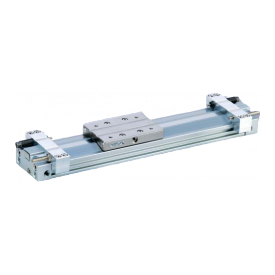
- Page 1 CAT.ES20-165 Mechanically Jointed Rodless Cylinders Basic short type (Rubber bumper) MY3A MY3A Series Series Basic standard type (Air cushion) MY3B MY3B Series Series Slide bearing type (Air cushion) MY3M MY3M Series Series Series Variations Series Variations Series Variations Stroke Bore size (mm) Piping Rubber Side...
- Page 2 High functionality with reduced height and length Mechanically Jointed Rodless Cylinders Series MY3A MY3A MY3A Basic short type (Rubber bumper) MY3B MY3B MY3B MY3B Basic standard type (Air cushion) Loading Capacity MY3M MY3M MY3A MY3A MY3M MY3M MY3M MY3M MY3B MY3B Slide bearing type (Air cushion)
- Page 3 Floating Bracket Easy connection with external guide. Vertical and lateral mounting is possible. (Page 16) Stroke Adjusting Unit (MY3A/3B) (MY3B/3M) Side Support The cylinder tube can be fixed from the upper or lower side. (Page 15, 27) Auto Switch Can be mounted on both sides from the front direction.
- Page 4 The MY3 series allow direct load application within the allowable range for the built-in guide. The payload in this case will vary depending on the driving speed and the mounting orientation of the cylinder. Please refer to the flow below and confirm the selection.
- Page 5 Note 3) Use the stroke adjusting unit of the MY3B series with an external guide. Note 4) Shown below are the details of the maximum operating speed for the stroke adjusting unit. MY3 Series, Maximum Operating Speed when Using the Stroke Adjusting Unit Unit: mm/s...
- Page 6 Series Types of Moment Applied to Rodless Cylinders Multiple moments may be generated depending on the mounting orientation, load and position of the center of gravity. Coordinates and Moments Load Weight and Static Moment Horizontal Ceiling Wall mounting mounting mounting : Yawing : Pitching Vertical...
- Page 7 Series Model Selection 2 The following are steps for selecting the MY3 series which is best suited to your application. Calculation of Guide Load Factor 1 Operating Conditions Mounting Direction Cylinder MY3A25-500 • • • • • • • • • • • • • • • • • • • • • • • • • • • • • • • • • • • • • •...
- Page 8 Series Calculation of Guide Load Factor 4 Calculation of Load Factor for Dynamic Moment Equivalent load F at impact υ δ —— = 1.4 = 1.4 x 300 x x 0.8 x 9.8 = 131.7 (N) : Moment υ max (from r of graph MY3A ⁄ M where 1.4 a = 420 mm/s) = 2.85 (N m) •...
- Page 9 MY3A Series Basic short type (Rubber bumper) ø16, ø25, ø40, ø63 MY3B Series Basic standard type (Air cushion) ø16, ø25, ø40, ø63...
- Page 10 MY3A/3B Series Model Selection The following are steps for selecting the MY3 series which is best suited to your application. Calculation of Guide Load Factor 1 Operating Conditions Mounting Direction Cylinder MY3A25-500 • • • • • • • • • • • • • • • • • • • • • • • • • • • • • • • • • • • • • •...
- Page 11 MY3A/3B Series Model Selection Calculation of Guide Load Factor 4 Calculation of Load Factor for Dynamic Moment Equivalent load F at impact υ δ —— = 1.4 = 1.4 x 300 x x 0.8 x 9.8 = 131.7 (N) : Moment υ...
- Page 12 MY3A/3B Series Maximum Allowable Moment / Maximum Allowable Load Maximum allowable moment (N m) Maximum allowable load (kg) Bore size Series (mm) MY3A MY3B The above values are the maximum allowable values for moment and load. Refer to each graph regarding the maximum allowable moment and maximum allowable load for a particular piston speed.
- Page 13 MY3A/3B Series Model Selection Cushion Capacity Absorption Capacity of Rubber Bumper (MY3A) MY3A16 MY3A25 Horizontal collision: P = 0.5 MPa Horizontal collision: P = 0.5 MPa 1000 1000 Load weight (kg) Load weight (kg) MY3A40 MY3A63 Horizontal collision: P = 0.5 MPa Horizontal collision: P = 0.5 MPa 1000 1000...
- Page 14 MY3A/3B Series Cushion Capacity Absorption Capacity of Air Cushion and Stroke Adjusting Unit (MY3B) MY3B16 MY3B25 Horizontal collision: P = 0.5 MPa Horizontal collision: P = 0.5 MPa 2000 2000 Maximum collision speed (H) Maximum collision speed (H, L) with fixed intermediate position with fixed intermediate position 1000 1000...
- Page 15 MY3A/3B Series Model Selection External Shock Absorber Selection When the positioning of the stop position is necessary or the absorption capacity of the built-in cushion is not sufficient, refer to the selection procedure below and consider the installation of an external shock absorber. Selection Confirmation Items with Use of External Shock Absorber MY3 63 q When the cylinder alone is used.
- Page 16 Mechanically Jointed Rodless Cylinder MY3A/3B Series ø16, ø25, ø40, ø63 Basic Type: How to Order 300 LS Basic Type Number of auto switches Short type 2 pcs. (Rubber bumper) 1 pc. Standard type “n” pcs. (Air cushion) Auto switch Cylinder bore size Without auto switch ∗...
- Page 17 MY3A/3B Series Mechanically Jointed Rodless Cylinder Specifications MY3A Bore size (mm) Fluid Action Double acting Operating pressure range 0.15 to 0.8 MPa Proof pressure 1.2 MPa Ambient and fluid temperature 5 to 60°C MY3B Cushion Rubber bumper (MY3A) / Air cushion (MY3B) Lubrication Non-lube Symbol...
- Page 18 MY3A/3B Series Construction MY3A i @1 @5 o Component Parts Component Parts Description Material Note Description Material Note Cylinder tube Aluminum alloy Hard anodized Spring pin Carbon tool steel Head cover Aluminum alloy Hard anodized Seal ring Brass Bearing Slide table Aluminum alloy Electroless nickel plated Special resin...
- Page 19 MY3A/3B Series Mechanically Jointed Rodless Cylinder Construction MY3B i @1 @9 !3 !4 !9 !0 @8 @7 @5 o Component Parts Component Parts Description Material Note Description Material Note Cushion boss Cylinder tube Aluminum alloy Hard anodized Aluminum alloy Chromated Head cover Aluminum alloy Hard anodized...
- Page 20 MY3A/3B Series ø16, ø25, ø40, ø63 Short Type: MY3A Bore size Stroke (Hexagon socket head plug) (LL) depth 4-ø counterbore ø through hole + Stroke Floating bracket mounting thread counterbore, thread depth from bottom counter bore depth 2 x 2- + Stroke (Hexagon socket head plug)
- Page 21 MY3A/3B Series Mechanically Jointed Rodless Cylinder ø16, ø25, ø40, ø63 Standard Type: MY3B Bore size Stroke (Hexagon socket head plug) (LL) 4-ø counterbore depth ø through hole Cushion needle + Stroke Floating bracket mounting thread counterbore, thread depth from bottom 2-ø...
- Page 22 MY3A/3B Series ø16, ø25, ø40, ø63 Standard Type: Stroke adjusting unit Shock absorber for low load + Adjusting bolt MY3B Bore size Stroke (Shock absorber stroke) Stroke adjusting unit (mm) Applicable cylinder Shock absorber model MY3B16 14.1 21.5 26.5 034.5 40.8 25.8 25.0...
- Page 23 MY3A/3B Series Mechanically Jointed Rodless Cylinder Side Support Side support A MY-S A øG øH Side support B MY-S B (mm) Model Applicable cylinder MY-S16 MY3A16 / MY3B16 63.6 M4 x 0.7 MY-S25 MY3A25 / MY3B25 M6 x 1 MY-S32 MY3A40 / MY3B40 11.7 M8 x 1.25...
- Page 24 MY3A/3B Series Floating Bracket Facilitates connection to other guide systems. Application Application Mounting direction q (to minimize the installation width) Mounting direction w (to minimize the installation height) Work piece Work piece Series MY3A Guide Guide Series MY3A Floating mechanism Floating mechanism Bracket Bracket...
- Page 25 MY3M Series Slide bearing type (Air cushion) ø16, ø25, ø40, ø63...
- Page 26 MY3M Series Model Selection The following are steps for selecting the MY3 series which is best suited to your application. Calculation of Guide Load Factor 1 Operating Conditions Mounting Direction Cylinder MY3M25-500 • • • • • • • • • • • • • • • • • • • • • • • • • • • • • • • • • • • • • •...
- Page 27 MY3M Series Model Selection Calculation of Guide Load Factor 4 Calculation of Load Factor for Dynamic Moment Equivalent load F at impact υ δ —— = 1.4 = 1.4 x 400 x x 3.0 x 9.8 = (N) : Moment υ...
- Page 28 MY3M Series Maximum Allowable Moment / Maximum Allowable Load Recommended direction of applying M moment Maximum allowable moment (N m) Maximum allowable load (kg) Bore size Model (mm) MY3M ∗ We recommend that the static M moment direction should be as illustrated. Adjustment side Also, when using the product in a wall mount application (m applied), we recommend that the mounting...
- Page 29 MY3M Series Model Selection Cushion Capacity Absorption Capacity of Air Cushion and Stroke Adjusting Unit MY3M16 MY3M25 Horizontal collision: P = 0.5 MPa Horizontal collision: P = 0.5 MPa Maximum collision speed with 2000 2000 Maximum collision speed with fixed intermediate position fixed intermediate position 1500 1500...
- Page 30 Mechanically Jointed Rodless Cylinder MY3M Series ø16, ø25, ø40, ø63 Slide Bearing Type: How to Order 300 LS Slide Bearing Number of auto switches 2 pcs. Slide bearing type 1 pc. “n” pcs. Auto switch Slide Bearing Cylinder bore size Without auto switch 16 mm ∗...
- Page 31 MY3M Series Mechanically Jointed Rodless Cylinder Specifications Bore size (mm) Fluid Action Double acting Operating pressure range 0.15 to 0.7 MPa Proof pressure 1.05 MPa Ambient and fluid temperature 5 to 60°C Cushion Air cushion Lubrication Non-lube Symbol +1.8 +2.8 1000 mm or less , From 1001 mm Stroke length tolerance...
- Page 32 MY3M Series Construction MY3M i #3 @9 #2 !3 !4 #8 #0 #1 @7 o !2 @6 Component Parts Component Parts Description Material Note Description Material Note Aluminum alloy Hard anodized Stainless steel Cylinder tube Backup spring Head cover Aluminum alloy Hard anodized Bearing adjusting rubber Slide table...
- Page 33 MY3M Series Mechanically Jointed Rodless Cylinder ø16, ø25, ø40, ø63 Slide Bearing Type: MY3M Bore size Stroke (Hexagon socket head plug) (LL) depth 4-ø counterbore ø through hole Cushion needle + Stroke 2 x 2- + Stroke (Hexagon socket head plug) (mm) Model MY3M16...
- Page 34 MY3M Series ø16, ø25, ø40, ø63 Slide Bearing Type: Stroke adjusting unit Shock absorber for low load + Adjusting bolt MY3M Bore size Stroke (Shock absorber stroke) Stroke adjusting unit (mm) Applicable cylinder Shock absorber model MY3M16 14.1 27.5 32.5 40.8 25.8 RB0806...
- Page 35 MY3M Series Mechanically Jointed Rodless Cylinder Side Support Side support A MY-S A øG øH Side support B MY-S B (mm) Model Applicable cylinder MY-S16 MY3M16 63.6 M4 x 0.7 MY-S25 MY3M25 M6 x 1 MY-S32 MY3M40 11.7 M8 x 1.25 MY-S40 MY3M63 14.8...
- Page 36 Series Auto Switch Specifications Note) The operating ranges are provided as guidelines including the hystere- Auto Switch Proper Mounting Position sis and are not guaranteed values (with approx. ±30% variations). They (at Stroke End Detection) may vary significantly with the surrounding environment. MY3A D-A9/D-A9 V D-F9 W/D-F9 WV...
- Page 37 Series Auto Switch Specifications Auto Switch Specifications Type Reed switch Solid state switch 3-wire: 100 µA or less, 2-wire: 0.8 mA or less Leakage current None Operating time 1.2 ms 1ms or less Impact resistance 300 m/s 1000 m/s Insulation resistance 50 MΩ...
- Page 38 Series Auto Switch Connections and Examples Basic Wiring Solid state 3-wire, NPN Solid state 3-wire, PNP 2-wire 2-wire (Solid state) (Reed) Brown Brown Brown Brown Load Load Indicator Load light Switch Switch Switch Black main main main protective Black circuit circuit circuit circuit,...
- Page 39 Reed Switch: Direct Mounting Style D-A90(V)/D-A93(V)/D-A96(V) For details about certified products conforming to Auto Switch Specifications international standards, visit us at www.smcworld.com. PLC: Programmable Logic Controller Grommet D-A90/D-A90V (Without indicator light) Electrical entry: In-line Auto switch part no. D-A90/D-A90V Applicable load IC circuit, Relay, PLC Load voltage 24 V...
- Page 40 Solid State Switch: Direct Mounting Style D-M9N(V)/D-M9P(V)/D-M9B(V) For details about certified products conforming to Auto Switch Specifications international standards, visit us at www.smcworld.com. Grommet PLC: Programmable Logic Controller D-M9 D-M9 V (With indicator light) 2-wire load current is reduced D-M9N D-M9NV D-M9P D-M9PV...
- Page 41 2-color Indication, Solid State Switch: Direct Mounting Style D-F9NW(V)/D-F9PW(V)/D-F9BW(V) For details about certified products conforming to Auto Switch Specifications international standards, visit us at www.smcworld.com. Grommet PLC: Programmable Logic Controller D-F9 W/D-F9 WV (With indicator light) D-F9NW D-F9NWV D-F9PW D-F9PWV D-F9BW D-F9BWV Auto switch part no.
- Page 42 Series Made to Order 1 M a d e t O r d e r Please contact SMC for detailed dimensions, specifications and delivery lead times. Made to Order Application List Long Helical Holder Copper-free stroke insert threads mounting bracket Series Type XB11...
- Page 43 Series Made to Order 2 M a d e t O r d e r Please contact SMC for detailed dimensions, specifications and delivery lead times. Holder mounting bracket ……………………… q, w -X416/X417 Stroke adjustment range MY3 B 300 L X416 Bore size –10...
- Page 44 Series Safety Instructions These safety instructions are intended to prevent a hazardous situation and/or equipment damage. These instructions indicate the level of potential hazard by labels of "Caution", "Warning" or "Danger". To ensure safety, be sure to observe ISO 4414 Note 1) , JIS B 8370 Note 2)
- Page 45 Series Auto Switch Precautions 1 Be sure to read this before handling. Design and Selection Warning Caution 1. Confirm the specifications. 1. Use caution when multiple cylinders (actua- tors) are used and close to each other. Read the specifications carefully and use the product appro- priately.
- Page 46 Series Auto Switch Precautions 2 Be sure to read this before handling. Design and Selection Mounting and Adjustment Caution Warning 5. Ensure sufficient clearance for maintenance 3. Pay attention to leakage current. activities. <Solid state switch> With a 2-wire solid state switch, current (leakage current) When designing an application, be sure to allow sufficient flows to the load to operate the internal circuit even when in clearance for maintenance and inspections.
- Page 47 Series Auto Switch Precautions 3 Be sure to read this before handling. Wiring Operating Environment Warning Caution 1. Never use in an atmosphere of explosive 4. Avoid incorrect wiring. gases. <Reed switch> The construction of the auto switch is not intended to prevent A 24 VDC switch with indicator light has polarity.
- Page 48 Series Auto Switch Precautions 4 Be sure to read this before handling. Operating Environment Caution 1. Avoid accumulation of iron debris or close contact with magnetic substances. The auto switches in an actuator may malfunction when a large accumulated amount of machining chips, welding spatter and or magnetically attracted material is located near the auto switch.
- Page 49 Series Specific Product Precautions 1 Be sure to read this before handling. For Actuator Precautions, refer to “Precautions for Handling Pneumatic Devices” (M-03-E3A). Caution on Design Mounting Warning Caution 1. A deceleration circuit or shock absorber may 1. Do not apply strong impacts or excessive be required.
- Page 50 Series Specific Product Precautions 2 Be sure to read this before handling. For Actuator Precautions, refer to “Precautions for Handling Pneumatic Devices” (M-03-E3A). Maintenance Handling Caution Caution Centralized Piping Port Variations 5. Conduct stroke adjustment with an adjust- ment bolt as follows: •...
- Page 51 Series Specific Product Precautions 3 Be sure to read this before handling. For Actuator Precautions, refer to “Precautions for Handling Pneumatic Devices” (M-03-E3A). Handling Caution 7. Do not fix and use the stroke adjusting unit at an intermediate position (MY3B/MY3M). If the stroke adjusting unit is fixed at an intermediate position, an error may result depending on the collision energy.
- Page 52 SMC'S GLOBAL MANUFACTURING, DISTRIBUTION AND SERVICE NETWORK EUROPE NORWAY SINGAPORE SMC Pneumatics Norway A/S SMC Pneumatics (S.E.A.) Pte. Ltd. AUSTRIA SMC Pneumatik GmbH POLAND SOUTH KOREA SMC Industrial Automation Polska Sp.z.o.o. SMC Pneumatics Korea Co., Ltd. BELGIUM SMC Pneumatics N.V./S.A. ROMANIA TAIWAN SMC Romania s.r.l.
Need help?
Do you have a question about the MY3 Series and is the answer not in the manual?
Questions and answers