Table of Contents
Advertisement
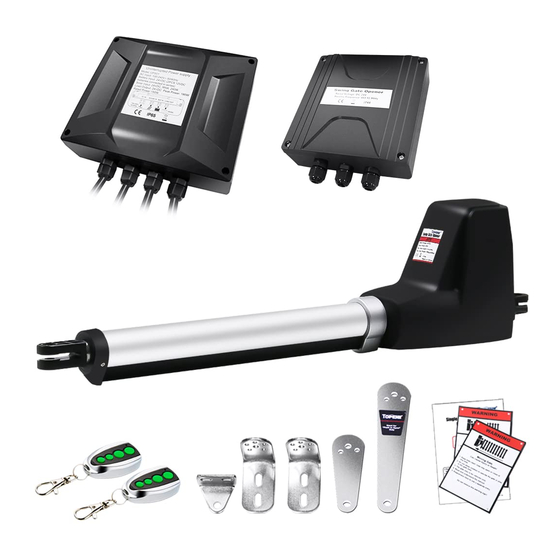
Single Swing Gate Opener
★ Please read and follow all warnings, precautions and instructions before
installation and use.
★ Coming with UPS01 uninterrupted power supply, this series gate opener can be
powered by AC 100-240V electricity directly. It is allowed to use additional battery
(NOT incl.) and solar panel (optional) as BACK-UP or MAIN power source with
this UPS01.
★ Never connect the solar panel to the control board directly to charge the battery.
★ Periodic checks of the opener are required to ensure safe operation.
★ Save this manual.
C030616
User's Manual
Model:
AT6131 / AT12131
AT6131S / AT12131S
TOPENS Website
www.topens.com
Email: support@topens.com
VER 22a
Advertisement
Table of Contents

Subscribe to Our Youtube Channel
Related Manuals for Topens AT6131


Summary of Contents for Topens AT6131
- Page 1 Single Swing Gate Opener User’s Manual Model: AT6131 / AT12131 AT6131S / AT12131S TOPENS Website www.topens.com Email: support@topens.com ★ Please read and follow all warnings, precautions and instructions before installation and use. ★ Coming with UPS01 uninterrupted power supply, this series gate opener can be powered by AC 100-240V electricity directly.
- Page 2 Visit: www.topens.com Please record the product model, your email address etc. in the spaces provided below. Refer to this list when contacting TOPENS for technical service or assistance with your automatic gate opener. Where did you purchase? (Amazon.com; Amazon.ca: Amazon.co.uk, Amazon.de; Other, Please...
-
Page 3: Table Of Contents
Parts List.................................... 3 Extra Parts for AT6131S / AT12131S..........................3 Accessories Parts (Included in some models, refers to the actual package)............4 Optional Accessories Parts List (Available at TOPENS Store)................4 Replacement Parts................................5 Tools Needed:................................... 5 Technical Specifications & Features..........................5 Installation Overview................................7... -
Page 4: Safety Installation Information
use on any pedestrian gate. Pedestrians must be Safety Installation Information supplied with a separate pedestrian access. 1. READ and FOLLOW all instruction. For an installation utilizing non-contact sensors The gate opener is intended for use with Class I (safety sensors), product manual... - Page 5 BEFORE digging. NOTE: TOPENS Gate Operator can be used for driveway gates made by steel, wood, vinyl, and shaped as panel, tube, and chain-link. While use on solid surface gates is NOT recommended. Solid surface gates have a high...
-
Page 6: Parts List
Parts List Extra Parts for AT6131S / AT12131S... -
Page 7: Accessories Parts (Included In Some Models, Refers To The Actual Package)
Accessories Parts (Included in some models, refers to the actual package) Optional Accessories Parts List (Available at TOPENS Store) TC186-R WiFi TC186 WiFi ERM12 External M12 Remote Control Smartphone Remote Smartphone Remote Receiver Control with Camera Control with Camera TEW3 Vehicle Sensor... -
Page 8: Replacement Parts
/ AT12131 / AT6131S / AT12131S Gate Opener UPS01 Uninterrupted MK01 Hardware Kit Power Supply WARNING: Changes or modifications not expressly specified by this user manual, TOPENS could void the warranty of this equipment. Tools Needed: ·Power Drill ·Tape Measure ·Open End Wrenches - 14# &17# or Adjustable Wrenches... - Page 9 These specifications are subject to change without notice. NOTE: “NR" indicates this size and weight combination is NOT recommended for one arm actuator. NOTE: Ball bearing hinges should be used on all gates weighing over 140kg (300 lbs). Features: ·Soft start and soft stop ·Emergency release key in case of power failure ·Fast selecting push/pull to open ·Stop in case of obstruction during gate opening.
-
Page 10: Installation Overview
Installation Overview Important: The second gate opener cable should be put into the PVC conduit (not provided) which is buried underground .This protects the cable from lawn mowers and string trimmers. -
Page 11: Preparation For Installation
Preparation for Installation There are two installation types for the gate opener, Pull-to-Open and Push-to-Open. In the Push-to-Open installation, gate opens out from the property. A Push-To-Open Bracket (PSO part) is required to be used for each gate. NOTE: Ensure the gate does not open into public areas. One more person will help when installing. The gate opener is mounted to the gate and to the gate post. - Page 12 1. Insert the bolts through the holes of post bracket and post pivot bracket as shown. Place washers and nuts on the bottom of the bolts and hand tighten. 2. Attach the gate bracket and post bracket assy. to the opener by inserting a clevis pin.
- Page 13 6. Sign the bolt-hole point on the gate post and gate. Do this by placing a punch or a sign in the middle of each bolt slot on the post bracket and the gate bracket. It allows slight adjustments to the post bracket. Then remove the opener and brackets assy.
-
Page 14: Install The Opener On The Gate - For Push To Open
12. Insert the release key, and turn the key 90° counterclockwise. This restores normal operation. NOTE: The setting of the PULL/PUSH TO OPEN of the control board should be in accordance with the installation. Install the Opener on the Gate – for Push to Open The position of Post Bracket is very important. - Page 15 1. Insert the bolts through the holes of post bracket and PSO part (push to open bracket) as shown. Place washers and nuts on the bottom of the bolts and hand tighten. 2. Attach the gate bracket and post bracket assy. to the opener by inserting a clevis pin.
- Page 16 6. Sign the bolt-hole point on the gate post and gate. Do this by placing a punch or a sign in the middle of each bolt slot on the post bracket and the gate bracket. It allows slight adjustments to the post bracket. Then remove the opener and brackets assy.
-
Page 17: Mounting Of The Control Box
12. Insert the release key, and turn the key 90° counterclockwise. This restores normal operation. NOTE: The setting of the PULL/PUSH TO OPEN of the control board should be in accordance with the installation. Mounting of the Control Box Use 4 deck screws (not provided) to install the control box. Even though the control box is waterproof designed, for safety reason and a longer service life, it is recommended to install the control box inside a secure surface and at least 100 cm (40 inches) above the ground to avoid being flooded or buried under snow. -
Page 18: Connection Of The Power Supply
Connection of the Power Supply A 24VDC AC-DC power supply is included in the kit. You can plug it to the AC socket to use it power up the gate opener directly if the AC electricity is accessible. You can also connect a 24VDC back-up battery (2*12VDC, connected in series to become 24VDC) to the power supply if the AC electricity is not stable. - Page 19 the control box refer to step 1 in this chapter. And then you can connect 2 PCS 12VDC batteries in series and then connect it to the UPS-01 power supply. Power Mode 3. Use the batteries as the power source, only use the solar panel to charge the batteries If the AC electricity is not available, then you can choose the batteries as the power source and use the solar panel to charge the batteries.
- Page 20 Power Mode 4. By AC electricity and back-up batteries, use the AC electricity and the solar panel to charge the batteries at the same time If you want to use the solar panel and the AC electricity to charge the batteries at the same time, firstly you can connect the UPS-01 power supply &...
-
Page 21: Connection Of The Control Board
Connection of the Control Board 1. Actuator Insert the stripped cable wires into the appropriate terminals on the opener terminals block. The red wire should be inserted into the “+MOTOR” terminal(#17), the black wire into “MOTOR-” terminal (#18), the blue wire into “DLMT”... - Page 22 2. UPS-01 Power Supply Before connecting this item, please refer to the chapter of “Connection of the Power Supply”. 3. Battery (not included) & Solar panel (Optional, ONLY included in AT6131S/AT12131S) Please connect them following the chapter of “Connection of the Power Supply”. 4.
-
Page 23: How To Program The Remote To The Opener
Each remote has four buttons, from top to bottom are separately A, B, C and D. You may use this remote to operate as many as 4 sets TOPENS swing gate openers or 1 set TOPENS sliding gate opener and 2 sets... -
Page 24: Wireless Keypad Programming
1. Use this remote to only operate TOPENS swing gate opener A, B, C and D four buttons share same function once they are programmed with TOPENS swing gate opener. You may choose any button to program it with our swing gate opener. -
Page 25: Adjusting The Limit Switch
Adjusting the Limit Switch Note: Before adjusting the limit switch, refer to the chapter of “Install the Opener on the Gate”, and make sure that the rod is fully retracted when the gate is in the fully open position (for Pull-to-Open installation), or in the fully closed position (for Push-to-Open installation). - Page 26 DIP Switch #1: Select push/pull to open If the gate opens into the property (pull to open), the DIP Switch is set to OFF (factory default setting). If your gate opens out from the property (push to open) the DIP Switch must be set to the ON position. Factory default setting is OFF.
-
Page 27: Maintenance
Potentiometer A is used to adjust the stall force the gate opener. Turn the potentiometer clockwise to increase the stall force, and turn it counter-clockwise to decrease the stall force. Potentiometer B is used to adjust the auto close time of the gate opener. Turn the potentiometer clockwise to increase the auto close time, and turn it counter-clockwise to decrease the auto close time. - Page 28 6. Check the control board. Replace the control board if necessary. 1. The selected force is too small to move the gate. Turn the Potentiometer Gate moves a little clock-wise to increase the force. and then reverse or 2. Disconnect the gate from the gate operator and check that the gate slides freely stop without any binding.
- Page 29 Your comments and suggestions are important to us as they help us provide the best possible service. Should you have any need to contact us, the info below will help you get in touch: TOPENS Website www.topens.com Contact Us: E-mail: support@topens.com Kindly include your Product Model, Purchasing Date &...
Need help?
Do you have a question about the AT6131 and is the answer not in the manual?
Questions and answers