Table of Contents

Related Manuals for LDG AT-1000PROII


Summary of Contents for LDG AT-1000PROII
- Page 1 AT-1000PROII OPERATIONS MANUAL MANUAL REV A LDG AT-1000ProII 1000W Automatic Antenna Tuner LDG Electronics 1445 Parran Road St. Leonard MD 20685-2903 USA Phone: 410-586-2177 Fax: 410-586-8475 ldg@ldgelectronics.com www.ldgelectronics.com PAGE 1...
-
Page 2: Table Of Contents
Manual Memory Store Status Check Application Notes Mobile Operation Internally Generated RF Noise MARS/CAP Coverage Operation with LDG Electronics M1000 External Meter Tuning Hints Theory of Operation Some basic ideas about impedance Transmitters, transmission lines, antennas, and impedance The LDG AT-1000ProII... -
Page 3: Introduction
INTRODUCTION LDG pioneered the automatic, wide-range switched-L tuner in 1995. From its laboratories in St. Leonard, Maryland, LDG continues to define the state of the art in this field with innovative automatic tuners and related products for every amateur need. -
Page 4: Specifications
1000 watts. Power levels that significantly exceed specifications will most likely damage or destroy your AT-1000ProII. If the tuner fails during overload, it could also damage your transmitter, amplifier, or transceiver. Be sure to observe the specified power limitations. -
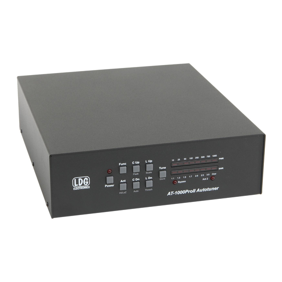
Page 5: Getting To Know Your At-1000Proii
FUNC button before pressing any other button will activate that button’s secondary function. The power button on the AT-1000ProII actually places the tuner in bypass and enters a low- power sleep mode, rather than turning the unit fully off. Press the Power button for 1 second to turn off, or momentarily to turn on. -
Page 6: Back Panel
• Tx: Connect a 50 ohm jumper coax from this jack to the ANT jack on the rear of the amplifier. • Ext. Meter: Connect the LDG M1000 External Meter to this jack, or use for remote control via PC. -
Page 7: Installation
1/8” stereo plug on the other end of the ICOM interface cable to the jack marked Radio on the rear of the AT-1000ProII. Connect the coaxial DC power plug of the ICOM interface cable to the 12V DC Power jack. - Page 8 PAGE 8...
- Page 9 Note: Optional Y-ACC cable has a red plug on the radio end of the cable, and a black plug on the tuner end. PAGE 9...
-
Page 10: Basic Operation
AT-1000ProII. In order to accommodate the many functions of the AT- 1000ProII, the operation performed by pressing a particular button is determined by the manner in which the button is pressed, and no operation begins until the button is actually released. - Page 11 Function mode times-out after a few seconds if no other button is pushed. Alternately, function mode can be cancelled by pressing the Func button again. In either case, when Function mode is exited, a “down arrow” is displayed on the LED display: Peak Mode On/Off: The Power display on the LED bargraph can display either average power or peak forward power, in watts.
- Page 12 To toggle between these two scales, press Func -> L Up. The LED marked “100” or “1000” will light momentarily to indicate the newly selected scale. Automatic Tuning Mode: The AT-1000ProII may be set for either semi-automatic tuning or fully automatic tuning. In semi-automatic tuning mode, a tuning cycle will not begin unless specifically requested by pressing the Tune button.
-
Page 13: Transmitting And Receiving
The default value of SWR threshold is 2.0:1. The following example shows setting the SWR threshold to 1.7:1. Antenna Selection: Press the Ant button momentarily to toggle which antenna port is currently active. The ANT 2 LED will light when Antenna 2 is selected, and is off when Antenna 1 is selected. -
Page 14: Tuning
2 Note that, while the AT-1000ProII employs software that prevents it from tuning while transmitting over 150 watts, it is still a good idea to bypass your amplifier while tuning, as further protection against damage to the tuner. -
Page 15: Manual Full Tune
25 watts or less before tuning. To explicitly initiate a full tuning cycle, press and hold the Tune button on the AT-1000ProII front panel for more than 2.5 seconds. The LEDs will display the following pattern to confirm a full tuning cycle is requested: If you are using one of the supplied radio interface cables, the radio will automatically reduce power, switch to CW mode, and begin transmitting while the full tuning cycle is in progress. -
Page 16: Bypass Mode
When in bypass, the Bypass LED is lit. If an ICOM radio and interface cable is used, the AT-1000ProII may also be bypassed by pressing the TUNER/CALL button momentarily. On some models of ICOM radios, changing bands will also automatically bypass the tuner. - Page 17 Additionally, if the forward power exceeds the maximum value selected for the meter scale, the PWR LEDs will blink an over-range condition. The four right-most LEDs of the PWR bargraph will cycle during over-range. PAGE 17...
-
Page 18: Advanced Operation
In some rare cases, after tuning, it may be desirable to adjust the the inductance and capacitance settings that the AT-1000ProII came up with during the tuning process. This is more likely to occur when attempting to tune an antenna far from its resonant frequency. -
Page 19: Status Check
SWR threshold value. While holding the Func button, the bargraph display will show the following pattern, to indicate that the AT-1000ProII is waiting for you to push a button to check its status: The following status items can be checked:... -
Page 20: Application Notes
APPLICATION NOTES Mobile Operation The AT-1000ProII is perfectly suited to mobile operation. It can be installed under the dashboard along with the transceiver, or mounted remotely. The only requirements are that the tuner remain dry, and that the power source is fused appropriately. A 2 amp “fast blow” fuse is recommended. -
Page 21: Operation With Ldg Electronics M1000 External Meter
Once the power level exceeds the relay protection threshold, the tuning cycle will stop, leaving the tuner in an un-tuned state. Because of this, LDG recommends switching the amplifer off before tuning, and then once tuning is complete, the AT1000ProII should be switched to semi-automatic mode (FUNC ->... -
Page 22: Transmitters, Transmission Lines, Antennas, And Impedance
“Ohm’s Law”, named for Georg Simon Ohm of Germany, who first discovered the principle in 1826. In RF circuits, an analogous but more complicated relationship exists. RF circuits also resist the flow of electricity. However, the presence of capacitive and inductive elements causes the voltage to lead or lag the current, respectively. - Page 23 SWR meter until a minimum SWR is reached. The LDG Electronics AT-1000ProII automates this process. No tuner will fix a bad antenna. If the antenna is far...
-
Page 24: The Ldg At-1000Proii
This allows the AT-1000ProII to handle loads that are either greater than or less than 50 ohms. All relays are sized to carry 1000 watts continuously. The relays are non-latching, so power is required to “hold”... -
Page 25: A Word About Tuning Etiquette
Be sure to use a vacant frequency when tuning. With today’s crowded ham bands, this is often difficult. However, causing interference to other hams should be avoided as much as possible. The AT-1000ProII’s very short tuning cycle, as little as a fraction of a second, minimizes the impact of tuning transmissions. -
Page 26: Quick Reference
QUICK REFERENCE Button Primary Func -> Button Status Check Function (Func Hold + Button) Full Tune (Long Press) Memory Tune Manually Store Display Relay (Medium Press) Tuning Tune Settings Parameters Bypass (Short Press) Toggle Display Toggle Antenna High/Low High/Low Selection Impedance Impedance Increase... -
Page 27: Technical Support
Ask your shipper for a tracking number or a delivery verification receipt. This way you know the product arrived safely at LDG. Be sure to give us your email address so our shipper can alert PAGE 27... -
Page 28: Product Feedback
(preferred) tell us how you used the product and how well it worked in your application. Send along a photo or even a schematic or drawing to illustrate your narrative. We like to share your comments with our staff, our dealers, and even other customers at the LDG website: http://www.ldgelectronics.com/...
Need help?
Do you have a question about the AT-1000PROII and is the answer not in the manual?
Questions and answers