
Related Manuals for LDG AT-11


Summary of Contents for LDG AT-11
- Page 1 AT-11 Automatic Antenna Tuner Assembly Manual Ver 2.4a LDG Electronics 1445 Parran Road St. Leonard MD 20685 Phone: 410-586-2177 Fax: 410-586-8475 ELECTRONICS e-mail: ldg@radix.net http://www.radix.net/~ldg...
- Page 2 It is lit when the tuner is trying to find a match. The AT-11 is a small to medium sized project. It should take the average builder an evening or two to complete (we averaged 6 hours on the prototypes). Besides the normal building tools needed (soldering iron or soldering pencil, wire cutters, screw drivers, ect), the only test equipment needed is an HF transceiver, dummy load (or resonant antenna) and voltmeter.
- Page 3 These "birdies" could be heard on a receiver at various places across the HF spectrum. The software was changed to allow the AT-11 to go into sleep mode and extinguish the birdies. The new software changes some of the operating features. At power on and in Semi mode, if there is no RF, there is no noticeable difference.
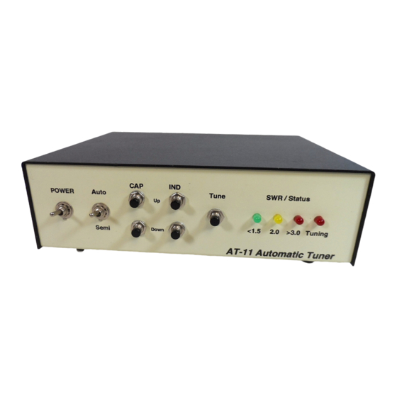
- Page 4 PC board to make them larger. Just about any metal enclosure that is 5.5 inches deep by 8 across by 2.5 inches high will work. See the front panel layout for ideas (figure 7). LDG also has custom finished enclosures available for around $30.
- Page 5 Once everything is mounted and wired, U1(the 68HC11) can be placed into the socket and power applied. Notice that U1 has a flattened corner that should match the socket. On power up, the AT-11 will flash all LEDs once to indicate that everything has initialized successfully. Current draw should be around 10 mA.
- Page 6 100 watts to the output. Adjust VR39 for 4.5 volts on test point REV. If you can’t get 100 watts out of your radio, use 10 watts and adjust for 1.5 volts. That's it, the AT-11 is now ready to be placed on the air.
- Page 7 A 40 meter dipole (at 30 feet) would tune anywhere from 3.1 to 30 MHz! We had some problems at 19 and 28 MHz finding a 1.5 match. The AT-11 usually found a 2.0, then we had to use the manual switches to get below 1.5.
- Page 8 Last Resort: As a last resort only, LDG Electronics will attempt to repair any problems. As much as we would like to do it for free, we just can't. We have a flat fee of $50 plus parts to repair an AT-11 (most resistors and capacitors are included in that fee).
- Page 9 If you have an idea of how the unit can be made better (in software or hardware), please send a description of your upgrade. If we use it for the AT-11, we'll send you a free upgrade. We can mention now that we do not have enough code space to implement tuning from memory or adding an LCD display (but we're working on it).
- Page 10 Fig.1 Block Diagram Input Output Inductors Sensor Hi/Lo Z-Switch Capacitors 68HC11 Microprocessor Switches LEDs User Interface Fig. 3 L3-8. L4 Shown. Fig. 2 L1-2. L2 Shown. Start here. Leave 1". Fig. 4 Inductor Table Inductor Turns Inches needed 10.0 Fig. 5 T1,10 turns #28 1.25 Green2 R e d 1...
- Page 11 Fig. 6 Capacitor Table Fig. 8 J3, Control Header Combination Voltage Capacitor pF (+/-5%) Ind Up Cap Up 10+10 C55+56 Ind Dn Cap Dn Yellow Green Red 2 Red1 1 KV Tune SW 1 KV Auto/Semi 1 KV 680+680 1 KV C62+63 1280 Fig.
- Page 12 3.3K 100pf 100K 10uf 78L05 82pf (151) (331) (681) (681) (681) Resistor 34064 68HC11 4148...
- Page 15 AT-11 Part t s List V2.4 List # Part Description L1-8 Iron Toroid T106-2 Ferrite Toroid FT-37-77 Wire #18 Thermeleze Wire #28 Red 8" Wire #28 Green 8" Wire #22 Bare 8" 68HC11A1FN 34064 78L05 8.0 Mhz Oscillator Socket1 52 Pin PLCC...
Need help?
Do you have a question about the AT-11 and is the answer not in the manual?
Questions and answers