
Related Manuals for LDG AT-1000Pro


Summary of Contents for LDG AT-1000Pro
- Page 1 LDG AT-1000Pro 1KW Automatic Memory Antenna Tuner Manual Version 1.0 LDG Electronics 1445 Parran Road St. Leonard, MD 20685 (410) 586-2177 ldg@ldgelectronics.com www.ldgelectronics.com...
-
Page 2: Table Of Contents
LDG AT-1000Pro 1KW Automatic Memory Antenna Tuner Table of Contents Introduction IMPORTANT TUNER SAFETY WARNINGS Jumpstart, or “Real hams don’t read manuals!” Specifications Operating Instructions Getting to know your AT-1000Pro Installation Setup Version Display: Tune Memory Clear Power-Up On/Off Function Modes Operation... -
Page 3: Introduction
LDG pioneered the automatic, wide-range switched-L tuner in 1995. From its laboratories near our Nation’s Capital, LDG continues to define the state of the art in this field with innovative automatic tuners and related products for every amateur need. -
Page 4: Jumpstart, Or "Real Hams Don't Read Manuals
Never exceed the rated specifications. 1. Connect your AT-1000Pro to a source of 11 – 15-volt DC power capable of supplying at least 1 Amp. Press the Power button to turn on the tuner (Power LED will be on). -
Page 5: Operating Instructions
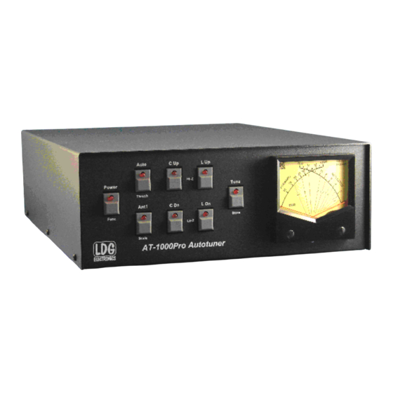
Operating Instructions Getting to know your AT-1000Pro Your AT-1000Pro is a quality, precision instrument that will give you many years of outstanding service; take a few minutes to get to know it. On the front panel, there are eight pushbutton switches: •... - Page 6 Forward and reflected power are indicted on individual scales. SWR is read at the intersection of the two needles, on the curved red scales across the center of the meter face. In the picture below, the meter is indicating an SWR of 2.0. On the back panel, there are six connections: •...
-
Page 7: Installation
1,000 watts, but they are readily available from many ham radio vendors. Your AT-1000Pro requires 11 – 15 volts DC at 1 Amp. If your radio runs on 12 volts DC, you can use the same power supply for your AT-1000Pro if it can provide the necessary 1 Amp current;... -
Page 8: Tune Memory Clear
Tune Memory Clear Press and hold the Power and Tune button while applying DC power, then release the buttons. This clears all tune memories, and is indicated by all the LEDs doing their version of the Finale from Riverdance. Memory is clear when the dance ends. Power-Up On/Off Press and hold the Auto button while applying DC to turn on the Power-Up On option. -
Page 9: Operation
Operation Button Functions and LED Indications Power: The Power button turns the tuner on and off. In the off state, the tuner is in bypass mode, routing RF from your transmitter or amplifier directly to Ant 2 with no matching. No buttons, except the Power button, will be active. -
Page 10: Normal Operation
To prepare the tuner for use, press the “Power” button on the front panel. The red LED above the button, and the meter lights come on, indicating that your AT-1000Pro has powered up. The tuner resets to the last tuned setting (and Antenna selection) before the previous power-down. -
Page 11: Fine-Tuning The Tuner
Error Indications The LEDs may indicate several error and status states: Power too low: your AT-1000Pro requires at least 5 watts to tune. If the power is too low, all LEDs will flash once. Loss of power during tune: if RF power is removed before a tuning cycle has ended, all LEDs will flash twice. -
Page 12: Led Error Codes
Power Up On/Off Radio Interface The AT-1000Pro includes interface cables for most Icom and the FT-857 (D) and FT-897(D) radios. The Icom interface will provide DC power to the tuner as well as control the keying of the radio during the tune cycle. The Yaesu interface will only control the keying of the radio. -
Page 13: Theory Of Operation
AT-1000Pro is doing, and how it does it. In simple DC circuits, the wire resists the current flow, converting some of it into heat. The relationship between voltage, current and resistance is described by the elegant and well-known “Ohm’s Law”, named for Georg Simon Ohm of Germany, who first described it in 1826. - Page 14 Simple tuners use variable capacitors and inductors. The operator adjusts them by hand while observing reflected power on the SWR meter until a minimum SWR is reached. Your LDG AT-1000Pro automates this process.
-
Page 15: The Ldg At-1000Pro
The LDG AT-1000Pro In 1995 LDG pioneered a new type of automatic antenna tuner. The LDG design uses banks of fixed capacitors and inductors, switched in and out of the circuit by relays under microprocessor control. A built-in SWR sensor provides feedback; the microprocessor following an algorithm searches the capacitor and inductor banks, seeking the lowest possible SWR. - Page 16 capacitors and inductors. The program checks LC combination to see if a 1.5 or lower SWR can be obtained, and stops when it finds a good match. The number of tuner adjustments is between 4 and 288. There are 1 to 16 checks for the coarse inductor tuning, 1 to 16 for the coarse capacitor and between 2 and 256 for the inductor and capacitor fine tuning.
-
Page 17: Care And Maintenance
Repairs average about 3 to 6 weeks. We will be glad to service your LDG product after the warranty period has ended. We will notify you of repair charges by phone or e-mail, and bill you after repairs are completed.
Need help?
Do you have a question about the AT-1000Pro and is the answer not in the manual?
Questions and answers