Summary of Contents for LDG AT-1000
- Page 1 AT-1000 Automatic Antenna Tuner Manual Version 1.0G LDG Electronics 1445 Parran Road, PO Box 48 St. Leonard MD 20685-2903 USA Phone: 410-586-2177 Fax: 410-586-8475 ldg@ldgelectronics.com www.ldgelectronics.com...
-
Page 2: Table Of Contents
IMPORTANT SAFETY WARNINGS Like all high power antenna tuners, your AT-1000 handles a great deal of RF energy. Very large RF currents flow through the tuner, and very high RF voltages are sometimes present. Your AT-1000 is designed to safely handle this RF power within its specifications, with a reasonable margin of safety. -
Page 3: Jumpstart, Or "Real Hams Don't Read Manuals
Never exceed specifications. Connect your AT-1000 to a source of 11 – 15-volt DC power capable of supplying at least 1 Amp, red lead positive. The tuner will automatically power up; pilot and meter lights will come on. -
Page 4: Operating Instructions
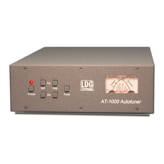
Operating Instructions Getting to know your AT-1000 Your AT-1000 is a quality, precision instrument that will give you many years of outstanding service; take a few minutes to get to know it. On the front panel, there are six pushbutton switches: •... -
Page 5: Installation
Your AT-1000 requires 11 – 15 volts DC at 1 Amp. If your exciter runs on 12 volts DC, you can use the same power supply for your AT-1000 if it can provide the necessary 1 Amp current; otherwise, you will need a separate power supply. -
Page 6: Basic Operating Instructions
50-ohm dummy load with a suitable power rating. You may tune your amplifier into the antenna through your AT-1000 providing it has tuned the antenna to a low SWR, and also providing you do not exceed the specified ratings of either your amplifier or your AT-1000. Never press the Tune button while transmitting more than 100 watts. - Page 7 Tune (>125 watts) The two 1000 watt mark bounce codes indicate that your AT-1000 has activated a self-protection mode. The tuner will not allow you to change any tuner setting if the input power exceeds 75 watts when the SWR is greater than 3, or when the input power exceeds 125 watts regardless of SWR.
-
Page 8: Troubleshooting And Faq
Troubleshooting and FAQ: My tuner will not tune on one band Your coax length may be an odd ¼ wavelength of the frequency that you are trying to tune. Lengthen your coax 3 to 6 feet (1 to 2 meters). My tuner will not tune on many bands and the meters exhibit erratic behavior You may have RF getting into the tuner via the power cable. -
Page 9: Theory Of Operation
AT-1000 is doing, and how it does it. In simple DC circuits, the wire resists the current flow, converting some of it into heat. The relationship between voltage, current and resistance is described by the elegant and well-known “Ohm’s Law”, named... - Page 10 The operator adjusts the them by hand while observing reflected power on the SWR meter until a minimum SWR is reached. Your LDG AT-1000 automates this process. No tuner will fix a bad antenna. If your antenna is far from resonance, the inefficiencies inherent in such operation are inescapable;...
-
Page 11: The Ldg At-1000
The LDG AT-1000 In 1995 LDG pioneered a new type of automatic antenna tuner. The LDG design uses banks of fixed capacitors and inductors, switched in and out of the circuit by relays under microprocessor control. A built- in SWR sensor provides feedback; the microprocessor searches the capacitor and inductor banks, seeking the lowest possible SWR. - Page 12 The relays operate from an external 12 volt DC power supply. The total current drawn by the AT-1000 depends primarily on the number of energized relays, with the maximum current drain being approximately 1 Amp. Although the microprocessor’s oscillator runs at 8 MHz, its internal bus speed is on one-fourth that, or 2 MHz.
-
Page 13: Care And Maintenance
If you need to return your AT-1000 to us for service, package it carefully, keeping in mind that we will re- use your packaging to return the unit to you. A self-addressed return-shipping label, while not required, will help insure speedy and accurate delivery of your repaired unit. -
Page 14: Feedback
AT-1000, we'll send you a free upgrade as a “thank you”. We encourage everyone who uses the AT-1000 to contact us (card, letter or e-mail preferred) telling us how well it works for you. We are also always looking for photographs of our products in use; we...


Need help?
Do you have a question about the AT-1000 and is the answer not in the manual?
Questions and answers