Table of Contents

Related Manuals for LDG AT-100ProII


Summary of Contents for LDG AT-100ProII
- Page 1 AT-100PROII OPERATIONS MANUAL MANUAL REV A LDG AT-100ProII 100W Automatic Antenna Tuner LDG Electronics 1445 Parran Road St. Leonard MD 20685-2903 USA Phone: 410-586-2177 Fax: 410-586-8475 ldg@ldgelectronics.com www.ldgelectronics.com PAGE 1...
-
Page 2: Table Of Contents
Table Of Contents Introduction Jumpstart, or “Real hams don’t read manuals!” Specifications An Important Word About Power Levels Important Safety Warning Getting to know your AT-100ProII Front Panel: Back Panel: Installation BASIC Operation Using the Front Panel Buttons User Configuration Options... -
Page 3: Introduction
AT-100ProII. Connect your antenna’s 50-ohm coax feedline to the ANT 1 jack on the rear of the AT-100ProII. Connect the supplied DC coax cable to the jack marked 12 VDC. Connect this cable to a DC source between 11 and 16 volts DC, 500 mA. -
Page 4: Specifications
Dimensions: 7.5” x 5.5” x 2.0”. Weight 1.5 pounds. AN IMPORTANT WORD ABOUT POWER LEVELS The AT-100ProII is rated at 125 watts maximum power input at most. Many ham transmitters and transceivers, and virtually all amplifiers, output well over 125 watts. Power levels that significantly exceed specifications will definitely damage or destroy your AT- 100ProII. -
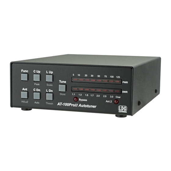
Page 5: Getting To Know Your At-100Proii
FUNC button before pressing any other button will activate that button’s secondary function. There is no power button on the AT-100ProII. When the tuner is idle, it enters a low-power sleep mode, drawing very little current. When the tuner detects a button press or an RF transmission, it “wakes up,”... -
Page 6: Back Panel
Back Panel: The rear panel of the AT-100ProII has six jacks. Ant 1: Connect a 50 ohm antenna coax feedline to this SO-239 connector. Ant 2: Connect a second 50 ohm antenna coax feedline to this SO-239 connector. Gnd (wing nut): Connect to the antenna system ground. -
Page 7: Installation
Installation The AT-100ProII is intended for indoor use only; it is not water-resistant. If you use it outdoors, (DXpedition to Bimini Island, for example) you must protect it from the weather. The AT-100ProII is designed for use with coax-fed antennas. If use with longwires or ladder-line-fed antennas is desired, an external balun is required. - Page 8 PAGE 8...
-
Page 9: Basic Operation
Function mode, which is done by pressing and releasing the Func button, and then pressing the desired button to activate the particular configuration option while in function mode. To confirm entry into Function mode, the AT-100ProII will flash an “up arrow” on the LED display after the Func button is pressed. - Page 10 Function mode times-out after a few seconds if no other button is pushed. Alternately, function mode can be cancelled by pressing the Func button again. In either case, when Function mode is exited, a “down arrow” is displayed on the LED display: Peak Mode On/Off: The Power display on the LED bargraph can display either average power or peak forward power, in watts.
- Page 11 To toggle between these two scales, press Func -> L Up. The LED marked “10” or “100” will light momentarily to indicate the newly selected scale. Automatic Tuning Mode: The AT-100ProII may be set for either semi-automatic tuning or fully automatic tuning. In semi-automatic tuning mode, a tuning cycle will not begin unless specifically requested by pressing the Tune button.
-
Page 12: Transmitting And Receiving
Transmitting and Receiving During receive operation, only the antenna indicator LED is normally lit on the AT-100ProII. During transmit, the forward RF power level is displayed on the PWR bargraph, and the SWR is displayed on the SWR bargraph. -
Page 13: Tuning
TUNING Basic Tuning Operation A tuning cycle on the AT-100ProII is initiated from either the Tune button on the front of the AT-100ProII, an over-SWR condition when in fully automatic tuning mode, or from pressing the TUNER/CALL button on the front of an ICOM radio connected using the ICOM interface cable. -
Page 14: Manual Full Tune
25 watts or less before tuning. To explicitly initiate a full tuning cycle, press and hold the Tune button on the AT-100ProII front panel for more than 2.5 seconds. The LEDs will display the following pattern to confirm a full tuning cycle is requested: If you are using one of the optional radio interface cables, the radio will automatically reduce power, switch to CW mode, and begin transmitting while the full tuning cycle is in progress. -
Page 15: Error Indication
Relays will not toggle if the SWR is over 3.0:1 while the power is over 125 watts. Remember that under no circumstances should you transmit more than 125 watts through the AT-100ProII. The diagrams on the next page show what the various error indications look like. - Page 16 Additionally, if the forward power exceeds the maximum value selected for the meter scale, the PWR LEDs will blink an over-range condition. The four right-most LEDs of the PWR bargraph will cycle during over-range. PAGE 16...
-
Page 17: Advanced Operation
In some rare cases, after tuning, it may be desirable to adjust the inductance and capacitance settings that the AT-100ProII came up with during the tuning process. This is more likely to occur when attempting to tune an antenna far from its resonant frequency. -
Page 18: Application Notes
SWR threshold value. While holding the Func button, the bargraph display will show the following pattern, to indicate that the AT-100ProII is waiting for you to push a button to check its status: The following status items can be checked:... -
Page 19: Conserving Power When Operating On Batteries
100ProII is idle, very little current is drawn. Internally Generated RF Noise The AT-100ProII is microprocessor controlled, and as such, generates a small amount of RF noise when the processor is active. Normally, the processor is only active during transmit operation, so the noise is not normally heard;... -
Page 20: Transmitters, Transmission Lines, Antennas, And Impedance
“Ohm’s Law”, named for Georg Simon Ohm of Germany, who first discovered the principle in 1826. In RF circuits, an analogous but more complicated relationship exists. RF circuits also resist the flow of electricity. However, the presence of capacitive and inductive elements causes the voltage to lead or lag the current, respectively. -
Page 21: The Ldg At-100Proii
THE LDG AT-100PROII In 1995, LDG Electronics pioneered a new type of automatic antenna tuner. The LDG design uses banks of fixed capacitors and inductors, switched in and out of the circuit by relays under microprocessor control. - Page 22 This allows the AT-100ProII to handle loads that are either greater than or less than 50 ohms. All relays are sized to carry 125 watts continuously. The relays are a latching type, and so they consume no current when not actively switching The SWR sensor is a variation of the Bruene circuit.
-
Page 23: Quick Reference
QUICK REFERENCE Button Primary Func -> Button Status Check Function (Func Hold + Button) Full Tune (Long Press) Memory Tune Manually Store Display Relay (Medium Press) Tuning Tune Settings Parameters Bypass (Short Press) Toggle Display Toggle Antenna High/Low High/Low Selection Impedance Impedance Increase... -
Page 24: A Word About Tuning Etiquette
LDG products our website also has complete product specifications and photographs you can use to help make your purchase decision. Don’t forget the links to all of the quality LDG Dealers also ready to help you make that purchase decision. -
Page 25: Out Of Warranty Service
Ask your shipper for a tracking number or a delivery verification receipt. This way you know the product arrived safely at LDG. Be sure to give us your email address so our shipper can alert you online when your product is en-route back to you. Please be assured that our staff makes every effort to complete repairs ahead of our published wait time.
Need help?
Do you have a question about the AT-100ProII and is the answer not in the manual?
Questions and answers