Table of Contents
Advertisement
Advertisement
Table of Contents

Subscribe to Our Youtube Channel
Related Manuals for LDG AT-7000


Summary of Contents for LDG AT-7000
- Page 1 AT-7000 Automatic Antenna Tuner For ICOM IC-7000 Manual Version 1.0 LDG Electronics 1445 Parran Road St. Leonard MD 20685 USA Phone: 410-586-2177 Fax: 410-586-8475 ldg@ldgelectronics.com www.ldgelectronics.com Copyright © LDG Electronics 2006. All rights reserved.
-
Page 2: Table Of Contents
LDG AT-7000 Automatic Antenna Tuner For ICOM IC-7000 Introduction Jumpstart, or “Real Hams Don’t Read Manuals!” Specifications An Important Word About Power Levels Getting To Know Your AT-7000 Installation Operation Application Notes Fixed Station Operation Expert Button Mobile Operation MARS/CAP Coverage... -
Page 3: Introduction
LDG pioneered the automatic, wide-range switched-L tuner in 1995. From its laboratories near the nation’s capitol, LDG continues to define the state of the art in this field with innovative automatic tuners and related products for every amateur need. -
Page 4: Specifications
• An Important Word About Power Levels The AT-7000 is rated at 125 watts maximum power input at most. Many ham transmitters and transceivers, and virtually all amplifiers, output well over 125 watts. Power levels significantly exceeding specifications will definitely damage or destroy your AT-7000. If your tuner fails during overload, it could damage your transmitter or transceiver. -
Page 5: Getting To Know Your At-7000
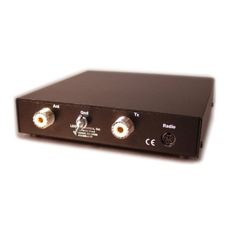
The process of storing tuning settings in memory is completely automatic; your AT-7000 literally “learns” as you use it, adapting itself to all of the bands and frequencies you use. If no memorized settings are available, the tuner runs a full tuning cycle,... - Page 6 On the back panel, there are four connectors: • RF input (marked “TX”, standard SO-239 socket) • Antenna connector (marked "Ant", standard SO-239 socket) • Interface jack (marked "Radio") for connecting the control cable to the IC-7000 or other compatible transceiver •...
-
Page 7: Installation
Connect the HF antenna jack on your IC-7000 to the TX jack on the back of your AT-7000 tuner using the provided coax jumper cable. Attach your antenna lead-in coax to the Ant jack on the back of your AT-7000 tuner. -
Page 8: Operation
TUNE icon will be on when the tuner was successful in obtaining a match of about 1.5 or less. On rare occasions, your AT-7000 may not be about to achieve a satisfactory match. This is usually due to a highly reactive antenna that is far from resonance. In this case, the tuner will go into bypass mode at the end of the tuning cycle, and the TUNE icon on the radio will be off. -
Page 9: Application Notes
Application Notes Fixed Station Operation Your AT-7000 operates well as a base-station tuner. You can position it on top of, or under the radio. Placing it elsewhere on your operating desk is possible, but you would need to “homebrew” a longer control cable; LDG does not provide a longer cable. Here is the control... - Page 10 Full Tune: Press the button for more than 2.5 seconds to start a full tuning cycle, even if parameters are stored for that frequency. As you hold the button down, the LED will light, then go out; release the button after the LED goes out. The LED will light during any tuning cycle.
-
Page 11: Mobile Operation
Mobile Operation Your AT-7000 is perfectly suited to mobile operation. You can install it under the dash along with your transceiver, or remotely in the trunk if you are using the IC-7000’s remote head capability. To install the unit under the dash, you can "homebrew" a bracket (LDG does not provide one). -
Page 12: Theory Of Operation
, but a little background will help you understand what your AT-7000 is doing, and how it does it. In simple DC circuits, the wire resists the current flow, converting some of it into heat. The relationship between voltage, current and resistance is described by the elegant and well-known “Ohm’s Law”, named for Georg Simon Ohm of Germany, who first discovered it in 1826. - Page 13 Simple tuners use variable capacitors and inductors; the operator adjusts them by hand while observing reflected power on the SWR meter until a minimum SWR is reached. Your LDG AT-7000 automates this process.
-
Page 14: The Ldg At-7000
The capacitors are connected to ground with the inductor relays. Another relay switches the entire capacitor bank to the input or output side of the inductor. This switching allows the AT-7000 to automatically handle loads that are greater than 50 ohms (high setting) and less than 50 (low setting). -
Page 15: A Word About Tuning Etiquette
All returns must be shipped to us pre-paid; we will not accept units with postage due. If you need to return your AT-7000 to us for service, package it carefully, keeping in mind that we will re-use your packaging to return the unit to you. Download the return form from our web site (www.ldgelectronics.com), fill it out and return it with your tuner.
Need help?
Do you have a question about the AT-7000 and is the answer not in the manual?
Questions and answers