Table of Contents

Related Manuals for LDG AT-100Pro


Summary of Contents for LDG AT-100Pro
- Page 1 AT-100PRO OPERATIONS MANUAL MANUAL REV B LDG AT-100Pro 100W Automatic Antenna Tuner LDG Electronics 1445 Parran Road St. Leonard MD 20685-2903 USA Phone: 410-586-2177 Fax: 410-586-8475 ldg@ldgelectronics.com www.ldgelectronics.com PAGE 1...
-
Page 2: Table Of Contents
Table Of Contents Introduction Jumpstart, or “Real hams don!t read manuals!” Specifications An Important Word About Power Levels Important Safety Warning Getting to know your AT-100Pro Front Panel: Back Panel: Installation Basic Operation Using the Front Panel Buttons Startup Options... -
Page 3: Introduction
AT-100Pro. 2. Connect your antenna’s 50-ohm coax feedline to the ANT 1 jack on the rear of the AT-100Pro. 3. Connect the supplied DC coax cable to the jack marked 12 VDC. Connect this cable to a DC source between 11 and 16 volts DC, 500 mA. -
Page 4: Specifications
• Dimensions: 7.5” x 5.5” x 2.0”. Weight 1.5 pounds. AN IMPORTANT WORD ABOUT POWER LEVELS The AT-100Pro is rated at 125 watts maximum power input at most. Many ham transmitters and transceivers, and virtually all amplifiers, output well over 125 watts. Power levels that significantly exceed specifications will definitely damage or destroy your AT-100Pro. -
Page 5: Getting To Know Your At-100Pro
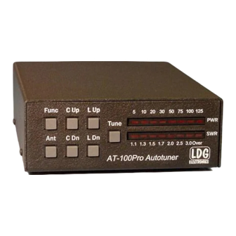
GETTING TO KNOW YOUR AT-100PRO Your AT-100Pro is a quality, precision instrument that will give you many years of outstanding service; take a few minutes to get to know it. Front Panel: The front panel of the AT-100Pro features seven push buttons and two LED bargraph scales: •... -
Page 6: Back Panel
There is no power button on the AT-100Pro. When the tuner is idle, it enters a low-power sleep mode, drawing very little current. When the tuner detects a button press or an RF transmission, it “wakes up,” ready to act. -
Page 7: Installation
DC coaxial power cable. This cable has a 2.5x5.5mm coaxial plug on the end. Plug the coaxial plug into the 12 VDC Power jack on the rear of the AT-100Pro, and connect the other end to a DC power source between 11 and 16 volts DC, capable of supplying up to 500 mA. - Page 8 PAGE 8...
-
Page 9: Basic Operation
ButtonA + ButtonB + ButtonC: The three buttons are held simultaneously. Startup Options The AT-100Pro has three commands that can only be issued when first applying DC power. That is, to issue these commands, first unplug the DC coax power cable, then hold down the appropriate button combination while plugging the DC coax power cable back in. -
Page 10: User Configuration Options
Function mode, which is done by pressing and releasing the Func button, and then pressing the desired button to activate the particular configuration option while in function mode. To confirm entry into Function mode, the AT-100Pro will flash an “up arrow” on the LED display after the Func button is pressed. - Page 11 The factory default is 125 watt full scale. Automatic Tuning Mode: The AT-100Pro may be set for either semi-automatic tuning or fully automatic tuning. In semi-automatic tuning mode, a tuning cycle will not begin unless specifically requested by pressing the Tune button.
-
Page 12: Transmitting And Receiving
Transmitting and Receiving During receive operation, no LEDs are normally lit on the AT-100Pro. During transmit, the forward RF power level is displayed on the PWR bargraph, and the SWR is displayed on the SWR bargraph. If the LED On/Off toggle is set to off, however, then no LEDs light up on transmit, to save battery power. -
Page 13: Tuning
TUNING Basic Tuning Operation A tuning cycle on the AT-100Pro is initiated from either the Tune button on the front of the AT- 100Pro, an over-SWR condition when in fully automatic tuning mode, or from pressing the TUNER/CALL button on the front of an ICOM radio connected using the ICOM interface cable. Two types of tuning cycles are available. -
Page 14: Manual Full Tune
2 An SWR rollback circuit automatically reduces the output power level when high SWR is present. Check your radio’s manual to see if your radio uses a rollback circuit. 3 The IC-756 Pro is an exception. If using the AT-100Pro with the IC-756 Pro, press the TUNE button on the AT-100Pro. -
Page 15: Error Indication
In some rare cases, after tuning, it may be desirable to adjust the the inductance and capacitance settings that the AT-100Pro came up with during the tuning process. This is more likely to occur when attempting to tune an antenna far from its resonant frequency. -
Page 16: High/Low Relay Adjustment
High/Low Relay Adjustment In addition to being able to manually control the inductor and capacitor value of the AT-100Pro, it is also possible to manually set the high/low impedance relay, which determines whether the tuner is an L-C configuration or a C-L configuration. To toggle the state of the high/low impedance relay, press Func ->... -
Page 17: Application Notes
APPLICATION NOTES Mobile Operation The AT-100Pro is perfectly suited to mobile operation. It can be installed under the dashboard along with the transceiver, or mounted remotely. The only requirements are that the tuner remain dry, and that the power source is fused appropriately. A 2 amp “fast blow” fuse is recommended. -
Page 18: Conserving Power When Operating On Batteries
For the absolute highest level of power savings, you can even remove the DC power plug from the AT-100Pro after it has found a tuning match, because the latching relays will maintain the tune setting even with no power applied. Just remember to plug the AT-100Pro back in when it’s time to re-tune. Internally Generated RF Noise The AT-100Pro is microprocessor controlled, and as such, generates a small amount of RF noise when the processor is active. - Page 19 The output circuit of a transmitter, the transmission line, and the antenna, all have a characteristic impedance. For reasons beyond the scope of this document, the standard impedance is nominally 50 ohms resistive, with zero capacitive and zero inductive components. When all three parts of the system have the same impedance, the system is said to be “matched”, and maximum transfer of power from the transmitter to the antenna occurs.
-
Page 20: The Ldg At-100Pro
The high/low impedance relay switches the capacitor bank either to the transmitter side of the inductor bank, or to the antenna side. This allows the AT-100Pro to handle loads that are either greater than or less than 50 ohms. All relays are sized to carry 125 watts continuously. - Page 21 The tuning routine uses an algorithm to minimize the number of tuner adjustments. The routine first de-energizes the high/low impedance relay if necessary, then individually steps through the inductors to find a coarse match. With the best inductor selected, the tuner then steps through the individual capacitors to find the best coarse match.
-
Page 22: Quick Reference
QUICK REFERENCE Button Primary Func -> Status Check Power-Up function Function Button (Func Hold + Button) Full Tune (Long Press) Memory Manually Tune Display Relay Tune (Store) Store Tuning (Medium Settings Parameters Press) Bypass (Short Press) Toggle Toggle Display Selected Ant (HiLoZ) Antenna High/Low... -
Page 23: Care And Maintenance
The outer case may be cleaned as needed with a soft cloth slightly dampened with household cleaning solution. As with any modern electronic device, the AT-100Pro can be damaged by temperature extremes, water, impact, or static discharge. LDG strongly recommends the use of a good quality, properly installed lightning arrestor in the antenna lead. -
Page 24: Returning Your Product For Service
Repairs can take six to eight weeks, but are usually faster. The most recent information on returning products for service is found at the LDG Customer Support Center. Send your carefully packaged unit with the Repair Form to: LDG Electronics, Inc. Attn: Repair Department 1445 Parran Rd St.
Need help?
Do you have a question about the AT-100Pro and is the answer not in the manual?
Questions and answers