Table of Contents

Subscribe to Our Youtube Channel
Related Manuals for LDG AT-200PROII


Summary of Contents for LDG AT-200PROII
- Page 1 AT-200PROII OPERATIONS MANUAL MANUAL REV B LDG AT-200ProII 200W Automatic Antenna Tuner LDG Electronics 1445 Parran Road St. Leonard MD 20685-2903 USA Phone: 410-586-2177 Fax: 410-586-8475 ldg@ldgelectronics.com www.ldgelectronics.com PAGE 1...
-
Page 2: Table Of Contents
Table Of Contents Introduction Jumpstart, or “Real hams don’t read manuals!” Specifications An Important Word About Power Levels Important Safety Warning Getting to know your AT-200ProII Front Panel: Back Panel: Installation Basic Operation Using the Front Panel Buttons User Configuration Options... -
Page 3: Introduction
The AT-200ProII is designed to handle 250 watts of output power, and is ideal for use with newer high-power transceivers. -
Page 4: Specifications
250 watts. Power levels that significantly exceed specifications will definitely damage or destroy your AT-200ProII. If the tuner fails during overload, it could also damage your transmitter, amplifier, or transceiver. Be sure to observe the specified power limitations. -
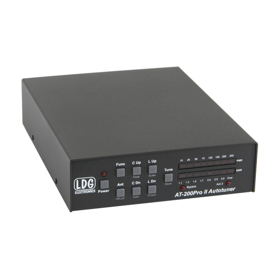
Page 5: Getting To Know Your At-200Proii
FUNC button before pressing any other button will activate that button’s secondary function. The power button on the AT-200ProII actually places the tuner in bypass and enters a low- power sleep mode, rather than turning the unit fully off. Press the Power button for 3 seconds to turn off, or momentarily to turn on. -
Page 6: Back Panel
Back Panel: The rear panel of the AT-200ProII has six jacks. • Ant 2: Connect your primary 50 ohm antenna coax feedline to this SO-239 connector. This antenna is selected and defaults to bypass when the tuner is off or DC power is removed. -
Page 7: Installation
200ProII, using a 50 ohm coax cable rated 200 watts or higher. Connect a 50-ohm antenna feedline coax to the ANT 2 jack on the back of the AT-200ProII, and optionally connect a second antenna feedline to the ANT 1 jack. - Page 8 PAGE 8...
- Page 9 Note: Optional Y-ACC cable has a red plug on the radio end of the cable, and a black plug on the tuner end. The radio end plugs into the ACC port on the radio. PAGE 9...
-
Page 10: Basic Operation
Function mode, which is done by pressing and releasing the Func button, and then pressing the desired button to activate the particular configuration option while in function mode. To confirm entry into Function mode, the AT-200ProII will flash an “up arrow” on the LED display after the Func button is pressed. - Page 11 Function mode times-out after a few seconds if no other button is pushed. Alternately, function mode can be cancelled by pressing the Func button again. In either case, when Function mode is exited, a “down arrow” is displayed on the LED display: Peak Mode On/Off: The Power display on the LED bargraph can display either average power or peak forward power, in watts.
- Page 12 To toggle between these two scales, press Func -> L Up. The LED marked “25” or “250” will light momentarily to indicate the newly selected scale. Automatic Tuning Mode: The AT-200ProII may be set for either semi-automatic tuning or fully automatic tuning. In semi-automatic tuning mode, a tuning cycle will not begin unless specifically requested by pressing the Tune button.
-
Page 13: Transmitting And Receiving
The default value of SWR threshold is 2.0:1. The following example shows setting the SWR threshold to 1.7:1. Antenna Selection: Press the Ant button momentarily to toggle which antenna port is currently active. The ANT 2 LED will light when Antenna 2 is selected, and is off when Antenna 1 is selected. -
Page 14: Tuning
TUNING Basic Tuning Operation A tuning cycle on the AT-200ProII is initiated from either the Tune button on the front of the AT-200ProII, an over-SWR condition when in fully automatic tuning mode, or from pressing the TUNER/CALL button on the front of an ICOM radio connected using the ICOM interface cable. -
Page 15: Manual Full Tune
TUNER/CALL button on the transceiver initiates a memory tuning cycle. The AT-200ProII will not tune if the transmit power is over 150 watts, or if the transmit power exceeds 100 watts during high SWR conditions, in order to protect the switching relays. -
Page 16: Error Indication
If an ICOM radio and interface cable is used, the AT-200ProII may also be bypassed by pressing the TUNER/CALL button momentarily. On some models of ICOM radios, changing bands will also automatically bypass the tuner. Error Indication When performing a tuning cycle, there are several conditions that may occur that cause the tune to fail. - Page 17 Additionally, if the forward power exceeds the maximum value selected for the meter scale, the PWR LEDs will blink an over-range condition. The four right-most LEDs of the PWR bargraph will cycle during over-range. PAGE 17...
-
Page 18: Advanced Operation
In some rare cases, after tuning, it may be desirable to adjust the inductance and capacitance settings that the AT-200ProII came up with during the tuning process. This is more likely to occur when attempting to tune an antenna far from its resonant frequency. -
Page 19: Status Check
SWR threshold value. While holding the Func button, the bargraph display will show the following pattern, to indicate that the AT-200ProII is waiting for you to push a button to check its status: The following status items can be checked:... -
Page 20: Application Notes
APPLICATION NOTES Mobile Operation The AT-200ProII is perfectly suited to mobile operation. It can be installed under the dashboard along with the transceiver, or mounted remotely. The only requirements are that the tuner remains dry, and that the power source is fused appropriately. A 2 amp “fast blow” fuse is recommended. -
Page 21: Application Hint For Tuning With The Kenwood Ts-480Hx
Application Hint for Tuning with the Kenwood TS-480HX On the Kenwood TS-480HX 200 watt radio, a built in feature of the radio makes it easy to tune quickly and safely. The TS-480HX has a programmable function key (PF key) on the front panel, that can be programmed to transmit a low power tuning carrier. -
Page 22: Theory Of Operation
, but a little background will help in understanding what the AT-200ProII is doing, and how it does it. In simple DC circuits, the wire resists current flow, converting some of it into heat. The relationship between voltage, current, and resistance is described by the elegant and well-known “Ohm’s Law”, named for Georg Simon Ohm of Germany, who first discovered the principle in... - Page 23 Simple tuners use variable capacitors and inductors; the operator adjusts them by hand while observing reflected power on the SWR meter until a minimum SWR is reached. The LDG Electronics AT-200ProII automates this process.
-
Page 24: The Ldg At-200Proii
This allows the AT-200ProII to handle loads that are either greater than or less than 50 ohms. All relays are sized to carry 250 watts PEP. -
Page 25: Quick Reference
QUICK REFERENCE Button Primary Func -> Button Status Check Function (Func Hold + Button) Full Tune (Long Press) Memory Tune Manually Store Display Relay (Medium Press) Tuning Tune Settings Parameters Bypass (Short Press) Toggle Display Toggle Antenna High/Low High/Low Selection Impedance Impedance Increase... -
Page 26: A Word About Tuning Etiquette
LDG products our website also has complete product specifications and photographs you can use to help make your purchase decision. Don’t forget the links to all of the quality LDG Dealers also ready to help you make that purchase decision. -
Page 27: Out Of Warranty Service
Ask your shipper for a tracking number or a delivery verification receipt. This way you know the product arrived safely at LDG. Be sure to give us your email address so our shipper can alert you online when your product is en-route back to you. Please be assured that our staff makes every effort to complete repairs ahead of our published wait time.
Need help?
Do you have a question about the AT-200PROII and is the answer not in the manual?
Questions and answers