
Related Manuals for Astoria 1GR


Summary of Contents for Astoria 1GR
- Page 1 CMA MACCHINE PER CAFFÈ S.R.L. DISPLAY ESPRESSO COFFEE MACHINE Use and Maintenance Manual. TECHNICIANS' instructions.
- Page 2 IMPORTANT: Read carefully before use. Store for future reference. All rights reserved on contents The total or partial reproduction and the dissemination of this document’s contents is forbid- den without the Manufacturer’s prior written authorisation. The Company logo is owned by the Manufacturer of the Machine.
- Page 3 SAFETY PRECAUTIONS Attention must be paid to the residual risks that are present during the operations de- LEVEL OF TRAINING AND scribed in the following paragraphs as they I.I. cannot be eliminated: KNOWLEDGE REQUIRED OF THE Compliance with the installation and ma- TECHNICIAN chine’s safety standards is dependent on the use, installation, maintenance and cor-...
- Page 4 INSTALLATION I.IV. safe and be able to carry out operations when the machine is not powered, the Tech- Electrical hazard nician must apply the rules prescribed by current technical standards (disconnect the High temperature hazard power supply, avoid reclosures, check that there is no voltage, etc.).
- Page 5 SHORT CIRCUIT FIRE • Do not place your hands or other body parts near the steam, hot water or milk In the event of a fire caused by the ma- dispensing nozzle tips. chine’s electrical system malfunctioning, adopt the following behaviours: If gas is used (where applicable), take spe- cial care with the following: • Disconnect the machine from the...
-
Page 6: Table Of Contents
General contents INTRODUCTION ..............9 6.13 Cup warmer ................42 6.14 Programming the “DISPLAY” version Guidelines for reading the Manual ........9 machine parameters .............43 Storing the Manual ..............9 6.15 Tips for a good cup of coffee ..........46 Method for updating the Instruction Manual ....9 MAINTENANCE AND CLEANING .........46 Recipients ..................9 Safety precautions ..............46... -
Page 7: Introduction
1. INTRODUCTION 1.2 Storing the Manual The Instruction Manual must be stored carefully. The manual Read this manual carefully. It provides important safety infor- should be stored, handled with care with clean hands and not mation to the Technician regarding the operations indicated placed on dirty surfaces. -
Page 8: Glossary And Pictograms
RECIPIENT QUALIFICATIONS Personal protective equipment (PPE) The machine is intended for a professional non-generalised Clothing or equipment worn by someone to protect their use, therefore the Technician must: health or safety. • Have attended the training courses organised by the Man- Intended use ufacturer relating to the type of machine;... -
Page 9: Guarantee
Calea Sagului, DN 59, KM 8+300 31058 SUSEGANA (TV) - ITALY 300516 TIMISOARA - ROMANIA Tel. +39 0438 6615 - Fax +39 0438 60657 Tel. +40 256 306 492/4 - Fax +40 256 306 496 E-mail: service@astoria.com E-mail: mce@mcesa.com Web-site: www.astoria.com Web-site: www.mcesa.com C.M.A. FRANCE... -
Page 10: Intended Use
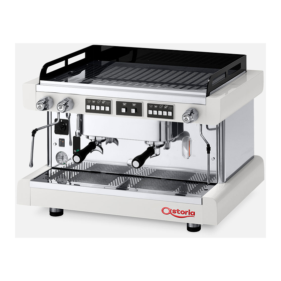
2.4 Intended use General safety features The Technician must be aware of accident risks, safety devices The espresso coffee machine has been designed to profes- and the general safety rules set forth in EU directives and by sionally prepare hot beverages such as tea, cappuccinos and the legislation of the country where the machine is installed. - Page 11 AL version AEP version 12 15 SAE - DISPLAY version Display TECHNICIANS' manual...
-
Page 12: Pushbutton Panels For The Aep & Sae Versions
2.6 Pushbutton panels for the AEP & SAE versions 1 espresso Manually dispensing Stop / Programming 2 espressos coffee / Continuous 1 medium coffee 2 large coffees 1 large coffee 2 medium coffees Manually dispensing coffee from Manually dispensing coffee from the left-hand group the right-hand group Dispensing Hot Water... -
Page 13: Pushbutton Panels For The Display Versions
2.7 Pushbutton panels for the DISPLAY versions Display Manually dispensing coffee from Manually dispensing coffee from the left-hand group the right-hand group Dispensing Hot Water Manually dispensing coffee from Dispensing Hot Water the left-hand group Dispensing via the automatic steam wand Exit programming Mode Decrease (-) -
Page 14: Internal Components
2.8 Internal components Heating unit 17. Heating unit thermostat Dispensing group 18. Heating unit pressure switch Internal motor pump (*) Heating unit/motor pump pressure gauge (*) Optional device Heating unit level-check window Internal pump water attachment connection (*) Manual water pump External pump water attachment connection Drain tray 10. -
Page 15: Data And Ce Marking
2.9 Data and marking The machine’s general technical data is provided in the fol- lowing table: TECHNICAL DATA TABLE COMPR. 120 V 2000-2330 W 2600-2930 W 2600-2930 W Power 220-240 V 2500-3500 W 3000-6650 W 3000-6650 W 4500-6700 W 5000-7350 W 380-415 V Frequency 50-60 Hz... - Page 16 2.9.1 Heating unit 2.9.3 Pressure relief safety valve The heating unit is made of copper sheet metal (1). The heat The pressure relief safety valve has a calibration exchangers are assembled onto this unit and are in turn con- of 0.19 MPa (1.9 bar) in order to ensure that the nected to the dispensing group.
- Page 17 2.9.7 LEVER group 2.9.8 Group with an EXTRACTABLE exchanger The group lever uses the heating unit pressure and water. This system does not require heat exchangers. The dispensing group heating is provided by direct contact When the lever (1) is lowered, the spring (2) inside the group with the heating unit.
- Page 18 2.9.9 CTS group 2.9.10 Safety thermostat (with a thermosiphonic circuit) The thermostat prevents any damage occurring to the elec- trical heating element if there is no water in the heating unit. In this system, the dispensing group (1) is heated by a ther- The thermostat bulb (7) is located inside a sheath (8) in the mosiphonic circuit (2) connected to the heat exchanger (3).
- Page 19 2.9.13 Automatic Water Entry 2.9.14 Volumetric dosing The Automatic Water Entry system is designed to check the The volumetric dosing device that is installed on the SAE ver- water level in the heating unit. It consists of: sions, measures the quantity of water sent to the group in order to dispense coffee.
- Page 20 2.9.17 Hot water spout 2.9.20 Water filter The hot water spout is connected to a heating unit suction In the mains water, non-soluble salts are hose. Depending on the model, hot water can be dispensed present which cause limestone to form in in two ways: the heating unit and other parts of the machine.
- Page 21 2.9.22 Automatic steam wand (optional) The “Automatic steam wand” system - fitted on some ver- sions with a display - enables milk to be automatically frothed at the programmed temperature. The operating principle of the automatic steam wand is listed below: • Press the specific button (1), located on the left side of the machine’s base.
-
Page 22: Transport And Handling
3. TRANSPORT AND HANDLING 3.5 Unpacking the machine Only remove the machine from its packaging when it is ready 3.1 Safety precautions to be installed, in order to prevent accidental collisions which could damage it: Carefully read the instructions provided in • Open the packaging, taking care not to damage the ma- chapter "I. -
Page 23: Storage
4. STORAGE 5. INSTALLATION 4.1 Overview 5.1 Safety precautions Carefully read the instructions provided in In the waiting period prior to installation, the machine must chapter "I. SAFETY PRECAUTIONS" on page be stored by the Manufacturer or an Authorised Distributor. If the technician has not performed all the in- 4.2 Storing the machine after operation stallation operations and the machine is then... -
Page 24: Installation And Operation Spaces
5.4 Installation and operation spaces 5.5 Support base Before the machine arrives, a suitable environment must be To ensure a sufficient degree of ergonomics and machine prepared: safety, a support base with the following features must be made available (reference drawings on the next page): • The appliance is not suitable for installation in an area where a water jet may be used. - Page 25 13. Motor pump inlet Support base 14. Motor pump outlet Grinder-dispenser 15. Water mains valve 16. Water mains check valve 50 cm minimum distance between the machine and the wall 17. Used coffee grounds drawer Drain tray 18. Support for knocking out the grounds in the filter holder Heating unit water level 19.
-
Page 26: Drilling The Support Base
5.6 Drilling the support base If holes need to be drilled into the support base to let the wa- ter inlet hoses, outlet hoses and power cables pass through, follow the directions given in the drawings below. 1 GROUP COMPACT 160 mm Front of the machine 326 mm... -
Page 27: Hydraulic Connection
5.7 Hydraulic connection Before connecting the hydraulic system, make sure the appliance has been disconnected from the electrical mains. Water supply 5.7.1 The appliance’s water supply must provide water which is suitable for human consumption, and must conform with the regulations in force in the place of installation. - Page 28 5.7.4 Electrical connection The water mains must supply cold water fit for human consumption (potable water) at a pres- • The conformity of the electrical system, effectiveness of sure between 0.15-0.6 Mpa (1.5 and 6 bar). If the the earthing system and functionality of the differential pressure is higher than 0.6 MPa (6 bar), connect a pressure circuit breaker - all of which are fundamental for guaran- reducer before the pump.
-
Page 29: Gas Connection (If Fitted)
The electrical system must be equipped with a FOR GERMANY protection device (8) that ensures an omnipolar The following requirements must be observed disconnection from the mains with a contact for installation: opening distance in overvoltage category III conditions • The regulation regarding the local police and the fire and which guarantees a suitable residual-current device, department. - Page 30 • If connecting with a hose, follow the instructions below: • When connecting with a rigid pipe: connect the Ø8 copper pipe to the 1/4 gas fitting (1). Use a hose that complies with the current regulations (it is important to periodically replace it as indicated • Check that the type of gas used corresponds to the one in- on the hose's stamp).
- Page 31 5.8.3 Gas table Instructions for installing the appropriate injector and adjust- ing the air extraction guard. Supply Injector inlet Burner Air intake extraction Minimum power Maximum power Maximum type pressure minimum pressure injector hole guard Q min consumption MODEL mbar mbar 1/100 mm kg/h...
-
Page 32: Commissioning
6. COMMISSIONING 5.8.4 Gas system connection To adjust the gas proceed as follows: 6.1 Safety precautions 1. Turn on the gas system. Carefully read the instructions provided in 2. Remove the locknut (A) and loosen the adjustment screw chapter "I. SAFETY PRECAUTIONS" on page (B) by turning it twice. -
Page 33: Lighting (If Fitted)
6.2.4 External motor pump adjustment 6.5 Automatic steam wand (if applicable) To adjust the operating pressure, proceed as follows: Adjusting the temperature 6.5.1 • Press a coffee dispensing switch. To program the temperature of the milk to be heated, enter • Adjust the pressure by turning the screw located on the the machine programming through the display and set the pump (3) so as to obtain a value between 0.8 and 0.9 Mpa... - Page 34 6.6.2 Electric heating The level window is replaced with a green indi- cator light (2) in some versions: when lit, it indi- (versions with a Display) cates the correct water level in the heating unit • Press the machine's main switch (1). and when it flashes slowly, it indicates that the water is being loaded.
-
Page 35: Water Renewal
6.6.3 Gas heating 6.7 Water renewal (if a gas system has been installed) When the machine is being installed, the Technician must re- place the water inside the hydraulic circuits by following these • Turn the power switch (A) to position 1. steps: • Open the gas valve (B) on the mains. • When the installation is complete, the appliance must be • Press and hold the button (C) and simultaneously press started, brought to the nominal working condition and... -
Page 36: Dispensing Coffee
6.8 Dispensing coffee • Whilst the lever is down, wait a moment (3-5 seconds) for the coffee to be pre-infused. Do not remove the filter holder from the dis- pensing group when coffee is being dispensed. The coffee dispensing method is different for each machine type; therefore, the instructions specific to the model being used must be followed. -
Page 37: Dispensing Steam
6.8.4 “SAE - DISPLAY” version • To confirm the dose, press the button again or the button. DISPENSING COFFEE • If desired, repeat this operation for the other dose but- • Place a cup/demitasse under the group’s dispensing spout. tons. • Press the desired dose button, e.g. and wait for the • When the programming is complete, press the but-... -
Page 38: Dispensing Hot Water
6.9.1 Control knob version To continuously dispense steam, move the lever in a vertical direction until it reaches the locked • Immerse the steam nozzle into the liquid to be heated. position, by hooking it in the constantly open po- • Rotate the valve knob anticlockwise. -
Page 39: Dispensing With The Automatic Steam Wand
6.10.2 “SAE - DISPLAY” versions 6.11.2 Dispensing Do not direct the steam towards hands or other DISPENSING HOT WATER parts of the body. Do not touch the steam noz- zles with bare hands; use the appropriate PPE. • Place the jug under the hot water nozzle. • Press the water button and wait for the hot water to be • Immerse the automatic steam wand nozzle tips (1) into... -
Page 40: Cup Warmer
6.13 Cup warmer 6.13.2 “SAE” version For safety reasons, we do not recommend plac- To use the cup warmer on this version of the machine, pro- ing cloths or other objects on the cup warmer ceed as follows: shelf in order to prevent the machine from over- • Place the cups on the cup warmer (1) shelf of the coffee heating. -
Page 41: Programming The "Display" Version Machine Parameters
6.14 Programming the “DISPLAY” version 1.0 BAR 115°C machine parameters 09:16 13-01-20 5 6.14.1 Accessing the menu (MODE) x 3 secs. • To access the programming menu, press and hold the CLOCK SETUP (MODE) button for at least 3 seconds. 09:16 18-10-12 1 • Use the (MODE) button to scroll the various areas of the programming menu. - Page 42 6.14.2 Programming the Clock 6.14.4 Programming a Working Day This menu is used to change the time, date and day of the This menu is used to programme the machine’s switch-off week: function for non-operating days. To set the machine’s shutdown days, follow the instructions • Enter the programming mode and scroll through the menu below.
- Page 43 6.14.5 Programming the Heating Unit 6.14.8 Displaying and resetting the litre Pressure counter This menu is used to program the heating unit pressure for This menu is used to display the litre counter and reset it: dispensing steam. • Enter the programming mode and scroll through the menu • Enter the programming mode and scroll through the menu until the litre counter is shown on the display.
-
Page 44: Tips For A Good Cup Of Coffee
7. MAINTENANCE AND CLEANING • Press and hold the ( + ) button for at least 3 seconds to confirm the reset operation. The above-indicated procedure can reset the 7.1 Safety precautions counts for single selections but not the ma- chine’s total counter (machine life cycle). Carefully read the instructions provided in chapter "I. - Page 45 Component Type of operation Quarterly Yearly Check the heating unit pressure which must be between 0.08 and 0.14 MPa (0.8 and 1.4 bar). PRESSURE GAUGE Periodically check the water pressure when coffee is being dispensed: check the pressure indicated on the gauge, which must be in the range of 0.8 to 0.9 MPa (8 and 9 bar).
- Page 46 Component Type of operation Quarterly Yearly PRESSURE GAUGE AND Check that the dosing device and pressure switch are working properly. PRESSURE SWITCH Check and clean the volumetric dosing device by removing any oxida- VOLUMETRIC DOSING DEVICE tion from the tips. MOTOR PUMP Visually inspect the condition of the machine’s wires.
-
Page 47: Water Filter Maintenance
7.3.6 NON-RETURN DRAIN VALVE check 7.4.2 Bypass configuration Depending on the hardness of the water, adjust the bypass of The non-return drain valve is an important component for the water filter as shown in the table below. Example: the correct operation of the machine. Perform the check as follows: 9°dKH water hardness • Activate the dispensing groups for about 30 seconds. - Page 48 7.4.3 Technical data Model Connection type 3/8" 3/8" 3/8" 3/8" Min.-max. water sup- ply pressure (bar) Min. - max. water 4-30 4-30 4-30 4-30 temperature (°C) Room temperature 4-40 4-40 4-40 4-40 min-max (°C) Total height (A) with- out bracket (mm) Total height (B) with the bracket (mm) Connection (C)
-
Page 49: Water Softener Regeneration
7.5 Water softener regeneration In order to keep the water softener, and hence the machine, in perfect operating condition, it is necessary to regularly re- It is very important to regenerate the softener within the es- generate it, depending on the softener and hardness of the tablished times. -
Page 50: Malfunctions And Solutions
7.6 Malfunctions and solutions Problem Cause Action • The general switch is in the "OFF" position. • Place the main switch in the "ON" position. • The machine switch is faulty. • Replace the main switch. NO MACHINE POWER • The mains switch is in the OFF position. •... - Page 51 Problem Cause Action • The group solenoid valve drain is clogged. • Clean the group drain. • The dispensing group is too cold. • Wait until the group has fully heated up. THE COFFEE GROUNDS ARE WET • The coffee has been ground too finely. •...
- Page 52 Problem Cause Action • The volumetric dosing device connection is • Check that the volumetric dosing device con- faulty. nector has been connected properly. • The electronic control unit connection is faulty. • Check that the connector (8/10 poles) has •...
-
Page 53: Cleaning Operations
7.7 Cleaning operations 7.7.2 Washing the cappuccino maker Take special care when cleaning the cappuccino maker and General instructions 7.7.1 follow the steps provided below: A few simple cleaning tasks are required to have a perfectly • Perform an initial wash by immersing the suction hose sanitised and efficient appliance. The instructions provided into the water and dispensing for a few seconds. - Page 54 7.7.4 Washing the dispensing group • When the button flashes to indicate that the wash cycle has been completed, remove both the filter holder Those in possession of the “AL” version of the and blind filter, then replace the coffee filter in the filter machine, must not perform the group wash op- holder. eration. • Reattach the filter holder to the dispensing group and press the button to start the rinse cycle.
-
Page 55: Display Warnings
7.7.5 Cleaning the group shower screen, 7.7.6 Cleaning the steam nozzle shower screen containment ring Weekly and filter holder Clean the steam nozzle as follows: Daily • Insert the nozzle into a jug with water and a specific cleaner, in accordance with the manufacturer's instruc- Clean the dispensing group and filter holder shower screens tions. -
Page 56: Spare Parts
9. SPARE PARTS 12. DISPOSAL To replace machine components and/or parts, refer to the of- 12.1 Disposal information ficial documentation provided by the Manufacturer. For the European Union and the European Economic Area only. All original spare parts are available from the Manufacturer’s website. The Manufacturer can provide a list of spare parts recommended for maintaining the various versions of the machine on re- quest. -
Page 57: Wiring Diagrams
13. WIRING DIAGRAMS 13.1 ELECTRIC MAINS connection Single phase 110-120 V / 220-240 V (*) For Brazil 3-CONDUCTOR CABLE Single phase 110-120 V / 220-240 V Single phase 110-120 V / 220-240 V 4-CONDUCTOR CABLE Three-phase 220-240 V Three-phase 380-415 V NE GR 5-CONDUCTOR CABLE (3-Phase+Neutral+Earth) Phase... -
Page 58: Machine Power Supply
13.2 MACHINE Power Supply (*) For Brazil (*) For Brazil NE B Phase Power cable Brown Phase Power switch Black Phase Connector Pressure switch Neutral Grey Heating element Earth Yellow-green Safety heating element Blue Switch TECHNICIANS' manual... -
Page 59: Al Version
13.3 AL version MA BL NE GR GV White Blue Power cable Heating unit Power switch Power supply connector Heating unit filling solenoid valve Fuse Grey Yellow-green Timeout LED Cup warmer switch Indicator light Brown Black Pressure switch Heating element RL30 AEA control unit (optional) Safety heating element... -
Page 60: Aep Version
13.4 AEP version MA BL NE GR GV White Blue Power cable Heating unit Power switch Power supply connector GR1 solenoid valve GR2 solenoid valve GR3 solenoid valve GR4 solenoid valve Heating unit filling solenoid valve FP1(*) UL (OPD) Motor pump fuse FP2(*) UL (OPD) Fuse for 230 V Fuse Grey... -
Page 61: Sae-Display Version
13.5 SAE-DISPLAY version Control unit Control unit Giemme Gicar Machine power supply code Paragraph Paragraph The table below shows, for each model of machine, the code 120 V 18090047 13.5.11 13.5.12 LISA R 1-2-3GR for the control unit and the reference to the page with the 230 V 18090048 13.5.11... - Page 62 13.5.1 Wiring diagram code 18365 - 18366 *JUNIOR* MA BL NE GR GV CN3 CN4 White Heating unit filling solenoid valve Heating element Blue Dispensing solenoid valve FP1(*) Power cable UL (OPD) Motor pump fuse Safety heating element FP2(*) Heating unit UL (OPD) Fuse for 230 V Heating unit level probe Membrane connection...
- Page 63 13.5.2 Wiring diagram code 18371010 - 18371011 *JUNIOR* MA BL NE GR GV White Heating unit filling solenoid valve Heating element Blue Dispensing solenoid valve FP1(*) Power cable UL (OPD) Motor pump fuse Safety heating element FP2(*) Heating unit UL (OPD) Fuse for 230 V Heating unit level probe Membrane connection Grey...
- Page 64 13.5.3 Wiring diagram code 18090065 - 18090066 *JUNIOR* MA BL NE GR GV White Blue Power cable Heating unit Pushbutton panel connection Tea button connection Pressure switch connection Heating unit level connection Volumetric counter connection RS232 serial network connection Power switch Power supply connector Volumetric counter Heating unit filling solenoid valve...
- Page 65 13.5.4 Wiring diagram code 18077 - 18078 - 18079 White Blue Power cable Heating unit Power switch Power supply connector MA BL NE GR GV Flow meter GR1 Flow meter GR2 Flow meter GR3 Flow meter GR4 GR1 solenoid valve GR2 solenoid valve GR3 solenoid valve GR4 solenoid valve...
- Page 66 13.5.5 Wiring diagram code 18090016 - 18090017 - 18090028 - 18090029 *GIEMME* White Blue Power cable Heating unit Power switch MA BL NE GR GV Power supply connector Flow meter GR1 Flow meter GR2 Flow meter GR3 Flow meter GR4 GR1 solenoid valve GR2 solenoid valve GR3 solenoid valve...
- Page 67 13.5.6 Wiring diagram code 18090016 - 18090017 - 18090028 - 18090029 *GICAR* White Blue Power cable MA BL NE GR GV Heating unit Serial connector Power supply Low voltage connector Steam outlet connector Power switch Power supply connector PB panel connector GR1 PB panel connector GR2 PB panel connector GR3 PB panel connector GR4...
- Page 68 13.5.7 Wiring diagram code 18090030 - 18090031 *GIEMME* White Blue Power cable Heating unit MA BL NE GR GV Steam outlet connector Power supply connector Low voltage connector Programm. connector PB panel connector GR3 CN10 PB panel connector GR2 CN11 PB panel connector GR1 Power switch Power supply connector Flow meter GR1...
- Page 69 13.5.8 Wiring diagram code 18090030 - 18090031 *GICAR* White Blue MA BL NE GR GV Power cable Heating unit Power supply connector PB panel connector GR1 PB panel connector GR2 PB panel connector GR3 Steam outlet connector Low voltage connector Power switch Power supply connector Flow meter GR1...
- Page 70 18090031A - 1 13.5.9 Wiring diagram code 18090031A *GIEMME* White Blue Heating unit Power switch Power supply connector Flow meter GR1 Flow meter GR2 Flow meter GR3 GR1 solenoid valve GR2 solenoid valve GR3 solenoid valve Filling solenoid valve Tea solenoid valve Inlet fuse (10 A) FP1(*) Motor pump fuse UL (OPD) fuse...
- Page 71 LEVEL LED connector INLET connector GR3 ow meter GR2 ow meter GR1 ow meter Heating unit level probe POWER SUPPLY connector - Phase TILL RS232 SERIAL connector Neutral +5 V/+VA TX_OUT RX_OUT PUSHBUTTON PANEL connectors RS232 TELEMETRY connector GR1 pushbutton panel +5 V/+VA GR2 pushbutton panel TX_MODBUS...
- Page 72 13.5.10 Wiring diagram code 18090031A *GICAR* MA BL NE GR GV White Blue Power cable Heating unit Power supply connector PB panel connector GR1 PB panel connector GR2 PB panel connector GR3 Steam outlet connector Low voltage connector Power switch Power supply connector Flow meter GR1 Flow meter GR2...
- Page 73 LEVEL LED connector INLET connector GR3 ow meter GR2 ow meter GR1 ow meter Heating unit level probe POWER SUPPLY connector - Phase BUTTON AND LED connector Neutral Button TEA button LED PUSHBUTTON PANEL connectors RS232 connector +5 V RS485A GR1 pushbutton panel CN10 RS485B...
- Page 74 13.5.11 Wiring diagram code 18090047 - 18090048 *GIEMME* White Blue MA BL NE GR GV CAL Heating unit CN1 Power supply connector CN2 Low voltage connector CN4 Serial transmission connector PB panel connector GR1 CN10 PB panel connector GR2 CN11 PB panel connector GR3 CN12 Power switch...
- Page 75 13.5.12 Wiring diagram code 18090047 - 18090048 *GICAR* White Blue Power cable MA BL NE GR Heating unit Power supply connector Low voltage connector Serial transmission connector CN10 PB panel connector GR1 CN11 PB panel connector GR2 CN12 PB panel connector GR3 CN14 Steam outlet connector CN18 Connector Warmer connect.
- Page 76 13.5.13 Wiring diagram code 18090079 - 18090080 MA BL NE GR TRPA JP16 CN14 JP17 JP18 JP15 JP14 JP12 RL10 CN13 TRF1 CN12 CN18 CN11 CN17 JP10 CN16 CN10 TECHNICIANS' manual...
- Page 77 Air pump supply Steam solenoid valve White Inlet fuse (6.3 A) Blue Motor pump fuse (500 mA) Power cable Air pump fuse (1 A) Heating unit FP1(*) UL (OPD) Motor pump fuse Power supply connector FP2(*) UL (OPD) Fuse for 230 V Low voltage connector Grey Display card conn.
- Page 78 18090080A - 1 13.5.14 Wiring diagram code 18090080A 400V TRPA USB1 CN14 JP12 CN13 CN18 CN17 CN12 JP20 JP11 RL10 CN16 CN11 JP10 CN15 CN10 Air pump supply GR2 solenoid valve Main switch Black White GR3 solenoid valve GR1 manual switch Vcc air pump Blue GR4 solenoid valve...
- Page 79 18090080A - 2 PUSHBUTTON PANEL connectors POWER SUPPLY connector Neutral GR1 pushbutton panel CN10 GR2 pushbutton panel Phase CN11 GR3 pushbutton panel CN12 GR4 pushbutton panel CN13 INLET connector GR4 ow meter GR3 ow meter GR2 ow meter GR1 ow meter OUTLET connector Heating unit safety probe Heating unit level probe...
- Page 80 13.5.15 Wiring diagram code 18090051 - 18090052 Milk pump supply White Blue Power cable MA BL NE GR Heating unit Power supply connector Low voltage connector Display card conn. connector Serial transmission connector Programm. connector ISP CN10 GR1 pushbutton panel connector CN11 GR2 pushbutton panel connector CN12...
- Page 81 13.5.16 Wiring diagram code 18090067-18090068 *CKX* White Blue Power cable Heating unit Power supply connector Diverter Heating unit filling S/L2 R/L1 solenoid valve V/T2 U/T1 Group solenoid valve Tea solenoid valve Grey Grey-red Yellow-green Switch Indicator light Brown Motor pump Black GS GS Group button...
- Page 82 13.5.17 Wiring diagram code 18090067-18090068 *CKXE** White Blue Power cable Heating unit Power supply connector Diverter S/L2 R/L1 Heating unit filling solenoid valve V/T2 U/T1 Group solenoid valve Tea solenoid valve Grey Grey-red Yellow-green Switch Indicator light Brown Motor pump Black Group button Jumper...
- Page 83 13.5.18 Wiring diagram code 18088000 - 18088001 White Blue Power cable Heating unit Power cable Power switch Pushbutton panel cable Power supply connector GR1 volumetric counter GR2 volumetric counter GR3 volumetric counter GR1 solenoid valve GR2 solenoid valve GR3 solenoid valve Heating unit filling solenoid valve Motor pump fuse Cup warmer fuse...
- Page 84 13.5.19 Wiring diagram code 18088004 - 18088005 White Blue Power cable Heating unit Power cable Power switch Pushbutton panel cable Power supply connector Tea button connection GR1 volumetric counter GR2 volumetric counter GR3 volumetric counter GR1 solenoid valve GR2 solenoid valve GR3 solenoid valve Heating unit filling solenoid valve Motor pump fuse...
- Page 85 13.5.20 Wiring diagram code 18090130 - 18090146 White MA BL NE GR GV Blue Power cable Heating unit Steam outlet connector Power supply connector Programming connector Heating unit NTC probe Low voltage connector GR2 pushbutton panel connector GR1 pushbutton panel connector Power switch Power supply connector GR1 volumetric counter...
-
Page 86: Hydraulic Diagrams
14. HYDRAULIC DIAGRAMS 14.1 LEVER GROUP hydraulic diagram Steam valve Hot water valve Negative pressure valve Safety valve Pressure switch Heating unit Dispensing group Heating unit heating element Valve 10 Optical level 11 Pressure gauge 12 Water inlet filter 13 Automatic Water Entry solenoid valve (optional) 14 Manual water inlet valve 15 Drain tray 16 Drain... -
Page 87: Aep Extractable Exchanger
14.2 AEP EXTRACTABLE EXCHANGER hydraulic diagram Internal motor pump Steam valve Hot water valve Negative pressure valve Safety valve Pressure switch Heating unit Optical level Pressure gauge Automatic Water Entry Solenoid Valve 10 Heating unit heating element 11 Heating unit drain valve External motor pump 12 Water inlet filter 13 Water dispenser... -
Page 88: Sae Extractable Exchanger
14.3 SAE EXTRACTABLE EXCHANGER hydraulic diagram Internal motor pump 1 Steam valve 2 Hot water valve 3 Negative pressure valve 4 Safety valve 5 Pressure switch 6 Heating unit 7 Optical level 8 Pressure gauge 9 Automatic Water Entry Solenoid Valve 10 Heating unit heating element 11 Dispensing group 12 Group solenoid valve... -
Page 89: Cts System Hydraulic Diagram - Aep
14.4 CTS SYSTEM hydraulic diagram - AEP Internal motor pump 1 Steam valve 2 Hot water valve 3 Pressure switch 4 Negative pressure valve 5 Safety valve 6 Heating unit 7 Heating unit heating element 8 Heat exchanger 9 Heating unit drain valve 10 Optical level 11 Pressure gauge 12 Automatic Water Entry Solenoid Valve... -
Page 90: Cts System Hydraulic Diagram - Sae
14.5 CTS SYSTEM hydraulic diagram - SAE Internal motor pump 1 Steam valve 2 Hot water valve 3 Pressure switch 4 Negative pressure valve 5 Safety valve 6 Heating unit 7 Heating unit heating element 8 Heat exchanger 9 Heating unit drain valve 10 Water inlet filter 11 Water dispenser 12 Optical level... -
Page 91: Credit-Debit Anddebit-Credit Systems
15. CREDIT-DEBIT and DEBIT-CREDIT SYSTEMS 15.1 CREDIT-DEBIT system 15.1.1 Installation Serial connection cable (supplied), code: 22556005 The CREDIT-DEBIT function is active in the PLUS1 electronic control units with the code 18090047-18090048 (without display), PLUS2 with code 18090079-18090080 (with dis- Serial transmission cable supplied code 22556004 play) and PLUS3 with code 18090051-18090052 (model (max. - Page 92 connector JP14 JP12 BLACK connector JP14 +5Vcc JP12 TECHNICIANS' manual...
- Page 93 15.1.2 Communication protocol Description of the operating principle with reference to the diagram shown below: • Order the beverage at the till. • The till sends the reserved selection-related code to the machine. • Select the ordered dose on the coffee machine. • The code that corresponds to the selection is sent to the till (see the code table).
- Page 94 15.1.3 Beverage selection code table DESCRIPTION SIGNAL RELAY I/O CONNECTOR REF. 1 GR1 Espresso 011 h CN7-1 1 GR1 Medium 012 h CN7-2 1 GR1 Large 013 h CN7-3 2 GR1 Espressos 014 h CN7-4 2 GR1 Medium 015 h CN7-5 2 GR1 Large 016 h...
-
Page 95: Debit - Credit System With Direct Connection To The Till
15.2 DEBIT - CREDIT system with direct connection to the TILL 15.2.1 Installation The DEBIT-CREDIT function is active in the PLUS1 electronic Serial connection cable (supplied), code: control units with the code 18090047-18090048 (without 22556005 display), PLUS2 with code 18090079-18090080 (with dis- play) and PLUS3 with code 18090051-18090052 (model with cappuccino maker/automatic steam wand) with a soft- ware programme dated 20/05/05 or later. - Page 96 connector JP14 JP12 BLACK connector JP14 +5Vcc JP12 TECHNICIANS' manual...
- Page 97 15.2.2 Communication protocol Description of the operating principle with reference to the diagram shown below: • Select the desired dose on the coffee machine. • The code that corresponds to the selection is sent to the till (see the code table). • The till replies with ACK=1H, thus enabling the beverage to be dispensed.
- Page 98 15.2.3 Beverage selection code table DESCRIPTION SIGNAL RELAY I/O CONNECTOR REF. 1 GR1 Espresso 011 h CN7-1 1 GR1 Medium 012 h CN7-2 1 GR1 Large 013 h CN7-3 2 GR1 Espressos 014 h CN7-4 2 GR1 Medium 015 h CN7-5 2 GR1 Large 016 h...
-
Page 99: Debit - Credit System With Connection To The Interface
15.3 DEBIT - CREDIT SYSTEM with connection to the INTERFACE 15.3.1 Beverage selection code table RELAY GROUP DOSE BUTTON Common HTW signals Common HTW signals ABHART* GND* TECHNICIANS' manual... - Page 100 15.3.2 PLUS 1-2 type (GIEMME type) system 34 33 08/05/05 R (Vcc+) N (GND) JP14 JP12 JP14 JP12 +5Vcc Components to be used for the INTERFACE - COFFEE MA- CHINE connection: • Code 26015 26-relay interface • Code 22550 Hartwall cable • Code 22551 Power cable • Code 22555 4-pole serial transmission cable Interface kit code WY83260002R.
- Page 101 15.3.3 PLUS 1-2 (GICAR type) system RL01 RL13 RL25 RL02 RL14 RL26 RL03 RL15 RL04 RL16 33 34 RL05 RL17 RL06 RL18 RL07 RL19 RL08 RL20 25 26 RL09 RL21 RL10 RL22 RL11 RL23 RL12 RL24 08/05/05 R (Vcc+) N (GND) JP14 JP12 JP14...
- Page 102 15.3.4 PLUS 3 type system RL16 RL15 RL14 RL13 RL12 RL11 RL10 RL24 RL23 RL22 RL21 RL20 RL19 RL18 RL17 39 40 RL32 RL31 RL30 RL29 RL28 RL27 RL26 RL25 08/05/05 R (Vcc+) N (GND) JP14 JP12 JP14 +5Vcc JP12 TECHNICIANS' manual...
- Page 103 Components to be used for the INTERFACE - COFFEE MA- DOSE RELAY I/O CONNECTOR REF. CHINE connection: 1 GR1 Espresso CN7-1 • Code 26016 32-relay interface 1 GR1 Medium CN7-2 • Code 22554004 Hartwall cable 1 GR1 Large CN7-3 • Code 22551 Power cable 2 GR1 Espressos CN7-4 • Code 22555 4-pole serial transmission cable...
- Page 106 CMA MACCHINE PER CAFFÈ S.R.L. Via Condotti Bardini, 1 - 31058 SUSEGANA (TV) - ITALY Tel. +39.0438.6615 - Fax +39.0438.60657 www.astoria.com - info@astoria.com Cod. 02000303 - Rev. 12 - 10/2020...
Need help?
Do you have a question about the 1GR and is the answer not in the manual?
Questions and answers