
Related Manuals for Digital Watchdog DWC-PTZ39XFM


Summary of Contents for Digital Watchdog DWC-PTZ39XFM
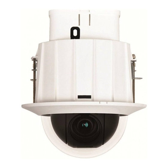
- Page 1 Super Speed Dome PTZ39XFM PTZ39X with In-Ceiling Mount User’s Manual Before installing and using the camera, please read this manual carefully. Be sure to keep it handy for future reference. Version 1.00...
- Page 2 Safety Information CAUTION RISK OF ELECTRIC SHOCK. DO NOT OPEN. CAUTION : TO REDUCE THE RISK OF ELECTRIC SHOCK, DO NOT REMOVE COVER (BACK). THERE ARE NO USER SERVICABLE PARTS INSIDE. REFER SERVICING TO QUALIFIED SERVICE PERSONNEL. Warning Precaution This symbol indicates that dangerous voltage This exclamation point symbol is intended to alert the consisting a risk of electric shock is present within user to the presence of important operating and...
- Page 3 Safety Information PRECAUTION Operating Before using, make sure power supply and others are properly connected. While operating, if any abnormal condition or malfunction is observed, stop using the camera immediately and then contact your Special dealer. Handling Do not disassemble or tamper with parts inside the camera. Do not drop or subject the camera to shock and vibration as this can damage the camera.
- Page 4 Safety Instructions Read these instructions. Keep these instructions for future reference. Heed all warnings. Follow all instructions. Do not use this camera near water. Clean only with a dry cloth. Unplug the camera from the wall outlet before cleaning. Do not block any ventilation openings to ensure reliable operation of the product ad to protect it from over-heating.
-
Page 5: Table Of Contents
Contents 1. Introduction Product & Accessories Part Name 2. Installation DIP Switch Setup Installation Cabling Check Points Before Operation 3. OSD Functions OSD DIsplay of Main Screen General Rules of Menu Operation ROOT MENU > SYSTEM INFORMATION DISPLAY SETUP > CAMERA ID DISPLAY SETUP >... -
Page 6: Introduction
Introduction - Product & Accessories Product Accessories Safety Wire X 2 CD with User’s Manual Dome Cover Quick Start Guide In-Ceiling Housing with PTZ Mechanism... -
Page 7: Part Name
Introduction - Part Name Dome Cover Hooks Dome Cover Side Hole Dome Cover PTZ Mechanism Hook PTZ Mechanism PTZ Mechanism Hook Guide In-Ceiling Housing Border Mounting Clip Bolt Mounting Clip Housing Safety Wire Hanger Junction Box Junction Box Hook In-Ceiling Housing Junction Box Cover Side Hole Junction Box Cover... -
Page 8: Installation
Installation - DIP Switch Setup Before installing the camera, you should PANASONIC set the DIP switch to configure the camera ID (Communication Protocol). Inner Box GE (Kalatel) AD (American Dynamics) Protocol Setup Baud Rate Setup RS-485 Termination Resistor - If you set the protocol as AUTO protocol, camera will automatically recognize the type of protocol being used;... - Page 9 Installation - DIP Switch Setup 2. Communication Baud Rate Setup 3. RS-485 Termination Resistor Select the appropriate baud rate with DIP switch combination. 2400 BPS - Factory Default - Pin 8 is used to control RS-485 termination. - Normally, it must be set to OFF state. - When you have trouble with long daisy chain style 4800 BPS connection, turn ON this termination switch for the last camera.
-
Page 10: Installation
Installation - Installation DETACH PTZ MECHANISM AND JUNCTION BOX COVER By pressing down and holding up the hooks located on both sides of the PTZ Mechanism, detach PTZ Mechanism from the housing. Then, detach the junction box cover by pressing down the hooks on both sides of the junction box. - Page 11 Installation - Installation CONNECT THE WIRES AND TERMINAL BLOCKS Connect the cables to terminal blocks and BNC located in the inner box of the junction box. See “Installation - Cabling” in the next section. Inner Box Main Connector Port Protocol, Address DIP Switch Alarm Out RS-485 Port...
- Page 12 Installation - Installation INSERT THE IN-CEILING HOUSING Insert the housing into the ceiling hole and press the edge of the housing against the ceiling. INSERT THE IN-CEILING HOUSING Fix the in-ceiling housing by turning the clip bolts located on the housing clockwise. INSERT THE PTZ MECHANISM Insert the PTZ mechanism into the upper housing by aligning the hooks of the PTZ mechanism to the hook...
- Page 13 Installation - Installation ATTACH THE DOME COVER Attach the dome cover by fixing the dome cover side hooks to the edge of the housing. DETACH THE PROTECTION VINYL DETACH THE DOME COVER Detach the dome cover from the cover side hole by using a flathead screwdriver or a coin.
-
Page 14: Cabling
Installation - Cabling Inner Box RS-485 BNC Cable (Keyboard Controller/DVR) Power Video Output RS-485 Communication (DVR/Keyboard) Power Connection For PTZ control, connect this line to keyboard and DVR. Please check the voltage and the current capacity of rated To control multiple cameras at the same time, the RS-485 power carefully. - Page 15 Installation - Cabling Inner Box Alarm Output Alarm Input Alarm Output In 1 In 8 Alarm Input/Sensor Alarm Output Sensor Input There are 4 alarm outputs, and they are the relay contact To use alarm input, select the typ eof sensor you wish to type.
-
Page 16: Osd
OSD - Check Points Before Operation Check Points Before Operation 1. Before power is applied, please check the cables carefully. 2. The camera ID of the controller must be identical to that of the camera you wish to control. Check the camera ID in “System Information”... -
Page 17: Functions
OSD - Functions Preset Group A maximum of 255 positions can be stored as preset The group function allows you to run a sequence of positions. The numbers 1 to 255 can be assigned as preset presets, patterns, and/or scans. numbers. -
Page 18: Osd Display Of Main Screen
OSD - OSD Display of Main Screen PRESET LABEL PATTERN 1 Preset Label Action Title CAMERA ID_TOP Camera ID_Top CAMERA ID_TOP CAMERA ID_BOT Alarm I/O Information Camera ID_Bottom CAMERA ID_BOT Compass Direction O 1234 23/MAR/2009 Date / Time I 12345678 24 00 00 Zoom Magnification 359/180/x100/SE... -
Page 19: General Rules Of Menu Operation
OSD - General Rules of Menu Operation The characters < >, that surround the menu item, indicate ROOT MENU that there is a sub menu. - - - - - - - - - - - - - - - - - - - - - - - - - - - <SYSTEM INFORMATION>... -
Page 20: Root Menu > System Information
OSD - ROOT MENU > SYSTEM INFORMATION ROOT MENU ROOT MENU ROOT MENU - - - - - - - - - - - - - - - - - - - - - - - - - - - - - - - - - - - - - - - - - - - - - - - - - - - - - - <SYSTEM INFORMATION>... -
Page 21: Display Setup > Camera Id
OSD - DISPLAY SETUP > CAMERA ID DISPLAY SETUP DISPLAY SETUP This menu defines what is displayed on the OSD of the main - - - - - - - - - - - - - - - - - - - - - - - - - - - ADDRESS screen. -
Page 22: Display Setup > Privacy Zone
OSD - DISPLAY SETUP > PRIVACY ZONE DISPLAY SETUP DISPLAY SETUP See the previous page. - - - - - - - - - - - - - - - - - - - - - - - - - - - ADDRESS CAMERA ID EDIT MASK - Move to Target Position... - Page 23 OSD - DISPLAY SETUP > PRIVACY ZONE PRIVACY ZONE - STYLE > COLOR Set the color of the mask. PRIVACY ZONE - - - - - - - - - - - - - - - - - - - - - - - - - - - Y-LEVEL 0 ~ 100 MASK NO.
-
Page 24: Motion Setup
OSD - MOTION SETUP MOTION SETUP MOTION SETUP Configures the general functions of pan/tilt motions. - - - - - - - - - - - - - - - - - - - - - - - - - - - PRESET LOCK PWR UP ACTION PRESET LOCK... - Page 25 OSD - MOTION SETUP ALARM INPUT SETUP MOTION SETUP If an external sensor is activated, camera will move to - - - - - - - - - - - - - - - - - - - - - - - - - - - PRESET LOCK the corresponding action.
-
Page 26: Function Setup > Preset Setup
OSD - FUNCTION SETUP > PRESET SETUP FUNCTION SETUP FUNCTION SETUP Configure 5 special functions with this menu. - - - - - - - - - - - - - - - - - - - - - - - - - - - <PRESET SETUP>... - Page 27 OSD - FUNCTION SETUP > PRESET SETUP LABEL PRESET SETUP - Edits the label to display on the monitor when camera arrives - - - - - - - - - - - - - - - - - - - - - - - - - - - PRESET NO.
-
Page 28: Function Setup > Scan Setup
OSD - FUNCTION SETUP > SCAN SETUP SCAN SETUP FUNCTION SETUP With the scan function, you can set the camera to move - - - - - - - - - - - - - - - - - - - - - - - - - - - <PRESET SETUP>... -
Page 29: Function Setup > Pattern Setup
OSD - FUNCTION SETUP > PATTERN SETUP PATTERN SETUP FUNCTION SETUP Pattern function is when a camera memorizes the path (mostly - - - - - - - - - - - - - - - - - - - - - - - - - - - curve path) created by a joystick controller and revives the path <PRESET SETUP>... -
Page 30: Function Setup > Group Setup
OSD - FUNCTION SETUP > GROUP SETUP GROUP SETUP SCREEN FUNCTION SETUP The group function allows you to run sequence of presets, pattern, - - - - - - - - - - - - - - - - - - - - - - - - - - - and/or scans. - Page 31 OSD - FUNCTION SETUP > GROUP SETUP EDIT GROUP - Selects Function Sequence EDIT GROUP When you finish setting up an ACTION, press Near or Enter key. - - - - - - - - - - - - - - - - - - - - - - - - - - - Move cursor up/down to select another ACTION NO.
-
Page 32: Function Setup > Schedule Setup
OSD - FUNCTION SETUP > SCHEDULE SETUP SCHEDULE SETUP SCREEN FUNCTION SETUP The schedule function allows you to run an appropriate function - - - - - - - - - - - - - - - - - - - - - - - - - - - like preset, scan, pattern, or group at a designated day and <PRESET SETUP>... - Page 33 OSD - FUNCTION SETUP > SCHEDULE SETUP EXAMPLE: SCHEDULE SETUP The second rule means camera will move to preset 12 at 7:00 - - - - - - - - - - - - - - - - - - - - - - - - - - - MASTER ENABLE every wednesday.
-
Page 34: Camera Setup > Wb Setup
OSD - CAMERA SETUP > WB SETUP ZOOM CAMERA SETUP ZOOM CAMERA SETUP Setup the general functions of zoom camera module. - - - - - - - - - - - - - - - - - - - - - - - - - - - FOCUS MODE SEMIAUTO DIGITAL ZOOM... - Page 35 OSD - CAMERA SETUP > WB SETUP WB SETUP - NIGHT WB SETUP - - - - - - - - - - - - - - - - - - - - - - - - - - - BRIGHTNESS LOW / MIDDLE / HIGH DAY/NIGHT...
-
Page 36: Camera Setup > Ae Setup
OSD - CAMERA SETUP > AE SETUP AE SETUP AE SETUP - - - - - - - - - - - - - - - - - - - - - - - - - - - IRIS <ALC> IRIS ALC / MANUAL DAY/NIGHT... - Page 37 OSD - CAMERA SETUP > AE SETUP DAY/NIGHT AE SETUP The camera automatically detects the change by the - - - - - - - - - - - - - - - - - - - - - - - - - - - IRIS <ALC>...
-
Page 38: Camera Setup > Special
OSD - CAMERA SETUP > SPECIAL SPECIAL ZOOM CAMERA SETUP Sets the special function(s) related to the image quality. - - - - - - - - - - - - - - - - - - - - - - - - - - - FOCUS MODE SEMIAUTO DIGITAL ZOOM... -
Page 39: System Setup
OSD - SYSTEM SETUP SYSTEM SETUP SYSTEM SETUP <DATE/TIME SETUP> - - - - - - - - - - - - - - - - - - - - - - - - - - - <DATE/TIME SETUP> Opens DATE/TIME SETUP menu. <RELAY TYPE>... - Page 40 OSD - SYSTEM SETUP SET HOME POSITION SET HOME POSOTION Home position means the origin of pan angle calculation. - - - - - - - - - - - - - - - - - - - - - - - - - - - The value of the pan angle displayed on the screen is based on this home position.
-
Page 41: System Initialize
OSD - SYSTEM INITIALIZE Initial Configuration Table SYSTEM INITIALIZE - - - - - - - - - - - - - - - - - - - - - - - - - - - Address CLEAR ALL DATA CLR DISPLAY SET Camera ID CLR CAMERA SET... -
Page 42: Specifications
Specifications - Dimension unit: mm 117.7 51.5 101.8 90.9 072.7 0211.8... -
Page 43: Specification Ptz39Xfm
Specifications - Specification PTZ39XFM Camera Image Device 1/4" Sony EX-View HAD Progressive Scan CCD 811 (H) × 508 (V) 410K Pixels Total Pixel 768 (H) × 494 (V) 380K Pixels Effective Pixel H. Resolution Color: 550 TV Lines B/W: 600 TV Lines S/N Ratio 52dB (AGC OFF) Zoom... - Page 44 Warranty Information Digital Watchdog (referred to as the “Warrantor”) warrants the Digital Watchdog camera against defects in materials or workmanship as follows: LABOR: For the initial two (2) years from the original purchase date, if the camera is determined to be defective, the Warrantor will display or replace the unit with a new or refurbished product at its option at no charge.
- Page 45 Limits and Exclusions There are no express warranties except as listed above. The warrantor will not be liable for incidental or consequential damages (including without limitation or damage to recording media) resulting from the use of these products or arising out of any breach of the warranty. All express and implied warranties, including the warranties of merchantability and fitness for particular purpose, are limited to the applicable warranty period set forth above.
- Page 46 5436 W Crenshaw St. Tampa, FL 33634 Tel : 866-446-3595 / 813-888-9555 Fax : 813-888-9262 www.Digital-Watchdog.com technicalsupport@dwcc.tv Technical Support Hours : Monday-Friday 8:30am to 8:00pm Eastern Time Correct Disposal of This Product (Waste Electrical & Electronic Equipment) (Applicable in the European Union and other European countries with separate collection systems) This marking on the product, accessories or literature indicates that the product and its electronic accessories (e.g.
Need help?
Do you have a question about the DWC-PTZ39XFM and is the answer not in the manual?
Questions and answers