Table of Contents
Advertisement
Quick Links
Advertisement
Table of Contents

Summary of Contents for adept technology T20
- Page 1 Adept T20 Pendant User's Guide...
- Page 3 Adept T20 Pendant User's Guide 10433-000 Rev. A February 2012 5960 Inglewood Drive • Pleasanton, CA 94588 • USA • Phone 925.245.3400 • Fax 925.960.0452 Otto-Hahn-Strasse 23 • 44227 Dortmund • Germany • Phone +49.231.75.89.40 • Fax +49.231.75.89.450 Block 5000 Ang Mo Kio Avenue 5 • #05-12 Techplace II • Singapore 569870 • Phone +65.6755 2258 • Fax +65.6755 0598...
- Page 4 The information contained herein is the property of Adept Technology, Inc., and shall not be reproduced in whole or in part without prior written approval of Adept Technology, Inc. The information herein is subject to change without notice and should not be construed as a commitment by Adept Technology, Inc.
-
Page 5: Table Of Contents
3.1 Using the Pendant Controls and Indicators 3.2 Enable Switch 3.3 Turning Power ON and OFF Turning Robot Power ON Turning OFF Power from the T20 Pendant 3.4 User Interface Operation User Interface Controls User Interface Flow Diagram Adept T20 Pendant User's Guide, Rev. A... - Page 6 4.6 Updating the Pendant Firmware 4.7 Displaying System Information 4.8 Displaying Recent Errors 4.9 Troubleshooting Critical Error 4.10 Cleaning 4.11 Periodic Maintenance Chapter 5: Technical Specifications 5.1 Dimension Drawings 5.2 Pendant Specifications Adept T20 Pendant User's Guide, Rev. A Page 6 of 50...
-
Page 7: Chapter 1: Introduction
Display robot position, system status, system identification, and error messages Display and change digital I/O System Compatibility The Adept T20 pendant is compatible with any robot that is controlled by the Adept Smart- Controller EX™ motion controller. 1.2 Dangers, Warnings, Cautions, and Notes There are six levels of special alert notation used in Adept manuals. -
Page 8: Safety Precautions
Power to the robot and its power supply must be locked out and tagged out before any maintenance is performed. Adept T20 Pendant User's Guide, Rev. A Page 8 of 50... -
Page 9: What To Do In An Emergency Situation
You have chosen a high-quality device that is equipped with highly-sensitive, state-of-the-art electronics. To avoid malfunctions or damage through improper handling, and possible void- ing of the warranty, follow these instructions during operation. Adept T20 Pendant User's Guide, Rev. A Page 9 of 50... -
Page 10: How Can I Get Help
Never place the Adept T20 pendant with the display screen facing down, to avoid dam- aging the buttons or display. Never place the Adept T20 pendant on an unstable surface. It could fall to the ground and be damaged. Never place the Adept T20 pendant close to heat sources or in direct sunlight. -
Page 11: Related Manuals
Chapter 1: Introduction Related Manuals This guide covers the installation, operation, and maintenance of the Adept T20 pendant. There are additional manuals that cover programming the system, reconfiguring installed com- ponents, and adding other optional components; see the table that follows. These manuals are available on the Adept Document Library CD-ROM shipped with each system. -
Page 13: Chapter 2: Installation And Setup
The Adept T20 pendant weighs 480 g (1.1 lb) without the adapter cable installed. 2.2 Before Unpacking the Pendant Carefully inspect the shipping packages for evidence of damage during transit. -
Page 14: Operating Environment
Installing the pendant and an Adept Front panel About Jumper Plugs There are two jumper, or bypass, plugs available for a T20 pendant system. One is a D-Sub plug (P/N 10052-000) for the XMCP connector on the Adept SmartController EX. The second is a screw-to-lock plug (P/N 10048-000) for the pendant adapter cable. - Page 15 Auto/Manual Mode with Both Front Panel and T20 Pendant Installed The Adept T20 pendant must be used with an Adept Front Panel. Note the following points: The E-Stop buttons on the Front Panel and T20 pendant both function and are individ- ually detected by the Adept SmartController EX.
-
Page 17: Chapter 3: Operation
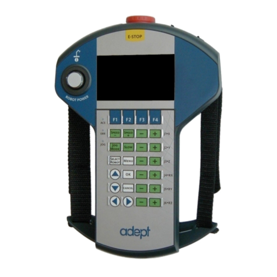
Chapter 3: Operation This chapter describes how to operate the Adept T20 pendant. Before proceeding, you need to perform the steps covered in the Installation and Setup chapter. 3.1 Using the Pendant Controls and Indicators Figure 3-1. T20 Pendant Controls and LEDs Adept T20 Pendant User's Guide, Rev. - Page 18 Chapter 3: Operation Table 3-1. Adept T20 Pendant Controls and LEDs Control Description Buttons/Switches E-Stop Button Press to stop program execution and turn off high power immediately. If the robot is equipped with brakes, activates the brakes. Robot Power Press to toggle between high power ON and OFF. Unlike the emer-...
-
Page 19: Enable Switch
NOTE: When power is disabled, the pendant automatically changes back to COMP mode. Note that: When power is off, the pendant cannot change out of COMP mode. The Power button is functional even when the screen saver is on (pressing Adept T20 Pendant User's Guide, Rev. A Page 19 of 50... -
Page 20: Turning Robot Power On
"panic" position), the system turns off in a controlled manner. This puts the system in a dif- ferent state than when the E-Stop button is pressed. To turn ON high power in this situation, perform the following procedure: Adept T20 Pendant User's Guide, Rev. A Page 20 of 50... -
Page 21: Turning Off Power From The T20 Pendant
Release the enable switch (this option is only available when the system is in Manual mode) 3.4 User Interface Operation This section describes how to use the T20 user interface to control the pendant. User Interface Controls Figure 3-3. T20 Pendant Indicators Adept T20 Pendant User's Guide, Rev. -
Page 22: User Interface Flow Diagram
NOTE: This indicator flashes when the robot number changes. User Interface Flow Diagram The following diagram shows the flow of the T20 pendant user interface. Please note the fol- lowing: The Home button always returns you to the T20 pendant user interface Home screen. - Page 23 Expanded Array Expanded Array Tool Display Info Error List (If the level above (If the level above was an array) was an array) Figure 3-4. User Interface Flow Diagram Adept T20 Pendant User's Guide, Rev. A Page 23 of 50...
-
Page 24: Displaying The Home Screen
Chapter 3: Operation Displaying the Home Screen Pressing the Menu button on the Adept T20 pendant, displays the Home screen as shown below. Figure 3-5. Home Screen The table below describes the soft keys shown on the Home screen. The soft keys are used for quick access to the different screens and functions on the Adept T20 pendant. -
Page 25: Using The Jog Controls
COMP mode, press the Jog Mode button until COMP is displayed in the Jog Mode indi- cator. NOTE: You cannot use jog control to move a robot while in COMP mode. Adept T20 Pendant User's Guide, Rev. A Page 25 of 50... -
Page 26: Joint Mode
“–” button to move the robot joint in the negative direction. World Mode When World mode is selected, movement in the X, Y, or Z direction is parallel to an axis of the World coordinate system. Adept T20 Pendant User's Guide, Rev. A Page 26 of 50... -
Page 27: Tool Mode
The Tool coordinate system is centered at the robot tool flange with the Z- axis pointing away from the flange. On most robots, the positive X-axis is aligned with the center of the tool flange key way. Adept T20 Pendant User's Guide, Rev. A Page 27 of 50... -
Page 28: Free Mode
As soon as another jog control mode is selected, all joints are returned to servo control and will not move freely. On some robots, Free mode is disabled for some of the joints. Adept T20 Pendant User's Guide, Rev. A Page 28 of 50... -
Page 29: Speed Control
While Slow speed is active, a red horizontal line and hash marks are displayed in the part of the speed indicator above 20%, showing that you cannot increase the speed beyond 20%. NOTE: The slow speed control is non-linear. Figure 3-10. Speed Indicator (Slow Mode) Adept T20 Pendant User's Guide, Rev. A Page 29 of 50... -
Page 30: Position Display
Press Grip to open and close a gripper installed on the tool flange. The signals for the gripper are configured in the Adept ACE software Gripper object signals. (For details on Adept T20 Pendant User's Guide, Rev. A Page 30 of 50... -
Page 31: Smart Locations
“tool” or “frame” in the Available Locations screen. If the option is disabled, all locations are shown on all three screens. See the examples in the following table. Table 3-4. Smart Locations Enabled versus Disabled Smart Locations Enabled Smart Locations Disabled Adept T20 Pendant User's Guide, Rev. A Page 31 of 50... -
Page 32: Available Frames
– this would produce either no movement (if the position is unreachable) or, possibly, movement to an arbitrary location, because the relative frame is no longer involved. Adept T20 Pendant User's Guide, Rev. A Page 32 of 50... -
Page 33: Available Tools
Press Null (F2) to set the current tool transformation (or offset) to null tool (no tool offset frame in use). 3.11 Location Teaching Press the Loc soft key from the pendant Home screen to display the Available Locations screen shown below. Adept T20 Pendant User's Guide, Rev. A Page 33 of 50... - Page 34 Shows the current position of the robot. Teach Teaches the current position to the selected location. Creates a new location named pendant.loc[X] where X is the first available value (1,2,3...). Adept T20 Pendant User's Guide, Rev. A Page 34 of 50...
- Page 35 Expand. The valid members of the selected array are dis- played. 2. Press the up/down arrow buttons to select the desired location. Press Cancel to return to the previous screen. Adept T20 Pendant User's Guide, Rev. A Page 35 of 50...
-
Page 36: Adding Approach Distance
ON (active, high) and OFF (inactive, low). Round icons represent input signals; square icons represent output signals. The available signal types are: digital output, digital input, soft, and robot. Adept T20 Pendant User's Guide, Rev. A Page 36 of 50... - Page 37 PgUp (Page Up)/PgDn (Page Down) to scroll through the signals. 3. For output signals, press Toggle to turn the selected signal ON or OFF. Figure 3-19. DIGITAL OUTPUT Screen Adept T20 Pendant User's Guide, Rev. A Page 37 of 50...
-
Page 38: Displaying And Clearing Errors
Displaying Recent Errors You can display a list of errors that have occurred since the pendant was last powered up. For details, see Displaying Recent Errors on page 43. Adept T20 Pendant User's Guide, Rev. A Page 38 of 50... -
Page 39: Chapter 4: Maintenance
Sets the approach distance (1 mm - 200 mm). For details, see Setting the Approach Distance on page 41. Update Firmware Updates the pendant firmware. For details, see Updating the Adept T20 Pendant User's Guide, Rev. A Page 39 of 50... -
Page 40: Using The Screen Saver
4. Press the up/down arrow buttons to select either "Normal" or "Slow" for the initial speed. 5. Press OK to accept the change; press Cancel to revert to the previous setting. Adept T20 Pendant User's Guide, Rev. A Page 40 of 50... -
Page 41: Enabling The Smart Locations
4.6 Updating the Pendant Firmware To update the pendant firmware: 1. Turn OFF power to the Adept SmartController EX or disconnect the Adept T20 pendant from the Adept SmartController EX (see Installation on page 14). 2. Insert a Micro SD card containing the firmware update files and "T20UpdatePackage.dat"... -
Page 42: Displaying System Information
1. From the Home screen, press Next to display Home screen 2. 2. From the Home 2 screen, press Maint (F3). The System Maintenance screen opens. 3. From the Maintenance screen, press Info (F1). The following screen opens. Adept T20 Pendant User's Guide, Rev. A Page 42 of 50... -
Page 43: Displaying Recent Errors
2. Press the Maint soft key followed by Errors (F2). The Recent Errors screen opens. 3. If necessary, press the up/down arrow buttons to select the error of interest. 4. Press Detail to display details about the selected error. Adept T20 Pendant User's Guide, Rev. A Page 43 of 50... -
Page 44: Troubleshooting
Figure 4-5. ERROR DETAIL Screen 5. Press List to return to the RECENT ERRORS screen. 4.9 Troubleshooting This section provides information on how to correct problems encountered while using the Adept T20 pendant. Adept T20 Pendant User's Guide, Rev. A Page 44 of 50... -
Page 45: Critical Error
Adept for assistance. 4.10 Cleaning To clean the Adept T20 pendant, use a soft cloth dampened with a small amount of water or a mild cleaning agent.. CAUTION: Never clean the Adept T20 pendant display screen or other sur- faces with solvents, abrasive cleaners, or scrubbing sponges. -
Page 47: Chapter 5: Technical Specifications
Chapter 5: Technical Specifications 5.1 Dimension Drawings Figure 5-1. Adept T20 Pendant Dimensions Adept T20 Pendant User's Guide, Rev. A Page 47 of 50... -
Page 48: Pendant Specifications
UL 94-V0 Environmental Operating 0° to 45° C (32° to 113° F) Temperature Storage Temperature -20° to 70° C (-4° to 158° F) Relative Humidity 5 to 95% (non-condensing) Adept T20 Pendant User's Guide, Rev. A Page 48 of 50... - Page 50 5960 Inglew ood D riv e Pleas anton, C A 94588 925 · 245 · 3400 PN: 10433-000 Rev A...
Need help?
Do you have a question about the T20 and is the answer not in the manual?
Questions and answers