
Related Manuals for Contec CNT24-2GY


Summary of Contents for Contec CNT24-2GY
- Page 1 PC-HELPER Isolated 24-bit Up/Down Counter Module for USB CNT24-2(USB)GY User’s Guide CONTEC CO.,LTD.
-
Page 2: Trademarks
No part of this document may be copied or reproduced in any form by any means without prior written consent of CONTEC CO., LTD. CONTEC CO., LTD. makes no commitment to update or keep current the information contained in this document. -
Page 3: Product Configuration
Serial Number Warranty Label Certificate Check the contents to make sure that you have everything listed below. If you do not have all the items or have any damage, contact your distributor or CONTEC group office where you purchased. CNT24-2(USB)GY... -
Page 4: Table Of Contents
Table of Contents Copyright ................i Trademarks ................ i Product Configuration ............ii Table of Contents ............. iii Copyright ................i Trademarks ................ i Product Configuration ............ii Table of Contents ............. iii 1. Introduction ..............1 Summary ................1 Features ................ - Page 5 Environment ............... 15 Installing the Utility ..........16 Connecting to a PC ............16 Setting Properties Using Device Manager ....18 Connecting to an External Device ......... 19 Signal Layout ............. 19 Connection Method ............ 20 Counting Function ............22 Counter Operating Modes .........
- Page 6 Stack Connection Locking Devices ......51 How the Stack Connection Locking Device Works ... 52 Connecting the Module ..........53 Removing the Module..........54 7. Product Specification ............ 55 Hardware Specification ..........55 Software Specification ............ 58 Circuit Block Diagram............ 59 Physical Dimensions ............
- Page 7 CNT24-2(USB)GY...
-
Page 8: Introduction
1. Introduction 1. Introduction Summary Before, the measurement and control was realized by way of inserting PCI interface boards into expansion slots of a desktop computer in case of configuring system using computers. However, because of the limit on number of expansion slots, it is difficult to configure system sometimes, or it is difficult to perform the same measure and control as PCI interface boards for a note PC. -
Page 9: Features
1. Introduction Being connected with USB port, the module can be setup simply. In addition, it can be used immediately owing to the supplied Windows development environment and Utility. The communication in Full Speed (12Mbps) is added to this USB module, and which is compatible with High Speed (480Mbps). - Page 10 1. Introduction Count-match output Once the count comparison value has been set, the module will output a signal to external when there is a match between a count value and a count comparison value. The allowable setting range of the output signal width is 0 - 104.5ms.
- Page 11 1. Introduction Easy to extend input channel By adding expansion modules sold separately, the number of input/output channels can be increased. It adopts the unique configuration of stack connecting which permits a simple, compact system configuration. CNT24-2(USB)GY + CNT24-2(FIT)GY x 3 (Up to 8 input channels can be extended) Easy-to-develop-application sample program Visual Basic, Visual C++, Delphi and C++ Builder...
-
Page 12: Support Software
: POW-AC13GY AC-DC power supply unit (input: 85 - 264VAC, output: 5VDC 2.0A) : POW-AD22GY DC-DC power supply unit (input: 10 - 30VDC, output: 5VDC 3.0A) : POW-DD10GY * Check the CONTEC’s Web site for more information on these options. CNT24-2(USB)GY... -
Page 13: Customer Support
In addition, you can also download sample programs in various languages. Limited One-Year Warranty CONTEC product is warranted by CONTEC CO., LTD.. to be free from defects in material and workmanship for up to one year from the date of purchase by the original purchaser. -
Page 14: How To Obtain Service
Please obtain a Return Merchandise Authorization Number (RMA) from the CONTEC group office where you purchased before returning any product. * No product will be accepted by CONTEC group without the RMA number. Liability The obligation of the warrantor is solely to repair or replace the product. In no event... -
Page 15: Handling Precautions
CONTEC will bear no responsibility for any problems, etc., resulting from modifying this product. - Please do not open this product casing. CONTEC will disclaim any responsibility for products whose casing has been opened. - Regardless of the foregoing statement, CONTEC assumes no responsibility for any errors that may appear in this document or for results obtained by the user as a result of using this product. -
Page 16: Environment
1. Introduction - Regarding “CE EMC Directive Notice”. Please see the “Hardware specification” to meet the mentioned standard above. The ferrite core must be installed in connecting cable so that this product may suit the above-mentioned standard. And USB connector must be earthed. Name Maker Turn... -
Page 17: Inspection
1. Introduction Inspection Inspect the product periodically as follows to use it safely. *The ventilation slits are not covered, and neither dust nor alien substance is attached to the ventilation slits LINK A B Z D1 PCOM EQ.P EQ.N PCOM EQ.P EQ.N *Make sure that the connectors... -
Page 18: Module Nomenclature
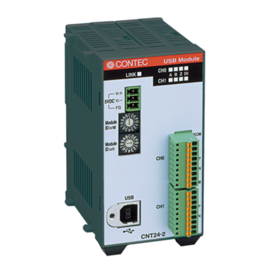
2. Module Nomenclature 2. Module Nomenclature Module Nomenclature Figures 2.1 shows the names of module components. In the figures, the indicated switch settings represent factory settings. CNT24-2(USB)GY LINK status LED Counter input status LED +5VDC input Module ID Counter input Counter input CH1 USB port Figure 2.1. - Page 19 2. Module Nomenclature Table 2.1. The List of Status LED Functions < CNT24-2(USB)GY > Name Function Indicator LED indicator color LINK status USB communication GREEN ON: Communication is established. status OFF: Communication is not established. Phase-A status Phase-A input status GREEN ON: when a current flows from pin PA (low level, negative logic)
-
Page 20: Setup
3. Setup 3. Setup Connection-Overall Diagram This is connection-overall diagram. Please reference to this page for actual connection. Connecting to an External Device Connecting to a PC (Page 19) (Page 16) Software Installation (Page 14) Connecting with Expansion Accessories (Page 51) Mounting on a DIN Rail (Page 35) Figure 3.1. -
Page 21: Setup Flow
3. Setup Setup Flow The following shows the basic flow for installing module. Software Installation Setting Properties Connecting to a PC -API-USBP(WDM) Using Device Manager -Installing USB driver Development -Setting device name Environment -Utilities Page 14 Page 16 Page 18 Software Installation Install software. -
Page 22: Installation Of Api-Usbp(Wdm) Development
3. Setup Installation of API-USBP(WDM) Development Environment Installation of development environment is namely installing supplied online help and sample program in all language in order to use API function. Clicking on “Install Development or Execution Environment”. [API-USBP(WDM) Installer] dialog box displays. Selecting “Advanced Counter input driver”. -
Page 23: Installing The Utility
It may cause a trouble in recognizing and operating the device according to the kind of USB hub. If you use the USB hub, we encourage you to take advantage of the CONTEC’s product loan service to confirm operation before purchasing. Step1 Setting supplied disk “API-USBP(WDM)”... - Page 24 3. Setup Step3 Starting “Found New Hardware Wizard” Start “Found New Hardware Wizard”, then select “Install from a list or specific location[Advanced]” item and finally click on “Next” button. In Windows Vista, Because the driver's installation is completed by "Installing the Software", it is not necessary to operate it about the Hardware Wizard.
-
Page 25: Setting Properties Using Device Manager
Step1 Starting Device Manager Right-click on [My Computer] and select [Properties] to start device manager. [XXXXX] within CONTEC Devices expresses the name from getting rid of GY from the model of module. In the case of Windows XP/2000 From [Start] menu, click on [Settings]-[Control Panel]-[System] and then click on [Device Manager] button in [Hardware] tab. -
Page 26: Connecting To An External Device
3. Setup Step3 Clicking on [OK] button Device name is set by clicking [OK] button. Points - When the application developed by users is running on an other PC, please perform foregoing operation on the target computer. (No need to install software introduced on next page) - Please use the device name specified in last step for initialization function when initialization is performed using API function. -
Page 27: Connection Method
3. Setup Connection Method When connecting this product to an external device, you can use the supplied connector plug. When wiring the Module, strip off approximately 7 - 8 mm of the covering for the cable, and insert the bare wire by pressing the orange button on the connector plug. - Page 28 3. Setup Connecting to a rotary encoder When the module is used with an external 5-V power supply, a current limiting resistor do not have to be inserted. When it is used with an external 12-V power supply, however, a resistor of about 400 ohms is required. Figure 3.5.
-
Page 29: Counting Function
3. Setup Counting Function The functions supported by this product is listed below. Because the count input multiplier and clear method can be set separately, the supported modes are as follows: single-phase input is of 1 mode, 2-phase input is of 6 modes, single-phase input with gate control is of 2 modes. - Page 30 3. Setup 2-phase input 2-phase pulse input refers to the input of two pulses, Phase-A (fast signal) and Phase-B (slow signal) that differ in phase by 90°. If phase-Z is provided (reference position signal), the counter can be cleared using 2-phase pulse input. Using rotary encoders and linear gauges, you can measure the moving distance.
- Page 31 3. Setup Setting rotary direction of the encoder DIR: count up in counterclockwise. The encoder count up in counterclockwise, so the counter data count down when the encoder turn in counterclockwise Phase-A (Phase-A/UP) Phase-B (Phase-B/DOWN) Phase-Z (Phase-Z/CLR) Count data FFFFFF FFFFFE FFFFFD 4 multiplier...
- Page 32 3. Setup Single-phase input with gate control The counter can be started/stopped according to the gate control signal that is input together with a string of single-phase pulses. The clear signal zero-clears the counter value. Because the pulses from an external signal can be measured in a segment of time, measuring the rotational velocity is practicable.
-
Page 33: Clearing Count Value
3. Setup Clearing Count Value Asynchronous clear The counter is zero-cleared when phase-Z is input, irrespective of the input state of phase-A or B. When phase-Z is set to positive logic, HIGH level is effective signal; When it is set to negative logic, LOW level is effective signal. - Page 34 3. Setup Point By the setting above, Phase-A and Phase-Z rise is detected within the module. First, check out phase-Z rise, clear the counter data at the next rise of phase-A. Even if the phase-Z input turns LOW before phase-A rises, the counter data will be cleared.
-
Page 35: Digital Filter
3. Setup Digital Filter According to the using environment, the Chattering Noise and Cross Talk may be presented in phase-A, B or Z of the counter. It would result in counting error. Use digital filter to avoid this abnormity. Digital filter clock setting data determines the sampling clock cycle for the digital filter. -
Page 36: Count-Match Output
3. Setup Count-match Output When there is a match between a count value on a channel and a count compare value, the pulse output is prepared to notify external device. The pulses width can be changed in the allowable range 0 - 104.45msec. -
Page 37: Connecting An External Power Supply Such As The Ac Adapter In Self-Powered Mode
3. Setup Connecting an External Power Supply Such as the AC Adapter in Self-powered Mode This product must be self-powered for use. For use in self-powered mode, use the +5-VDC input terminal. Power supply (5V) Power supply (GND) 5VDC Frame ground Figure 3.15. - Page 38 3. Setup Table 3.2. Optional power supply Physical dimension DIN rail Type Model Input Output (mm) AC adapter POA200-20-2 90 - 264VAC 5.0VDC ± 5% 47.5(W) x 75(D) x 27.3(H) (Bundled) 2.0A(Max.) (No protrusions) AC-DC power POW-AD13GY 85 - 132VAC 5.0VDC ± 5% 52.4(W) x 64.7(D) x 94.0(H) Corresponding supply...
- Page 39 3. Setup For the power supply for installation on a DIN rail, use the connector MC 1,5/3-ST-3,5 (Phoenix Contact). Connecting method - To connect the external power supply and USB cable to the unit, take the steps below: (1) Connect the external power supply connector to supply power to the module.
-
Page 40: Installing The Module
3. Setup Installing the Module Installation Orientation Please use the module following orientation illustrated in the graph when the module is mounting on a DIN rail and being used on a desk. It should be noted that lateral slit of the module being covered brings about malfunction. In addition, please use the supplied two rubber feet when setting on a desk or others as figure 3.18(A). -
Page 41: Mounting With Magnets
3. Setup Mounting with magnets Two magnets are appended to this product. It is easy of attachment and removal of the module to metal sides, such as a desk, partition panel and so on. Initial adhesion strength of seal is high, but adhesion strength decreases an ability of peeling strength if once removing a magnet from the enclosure of module. -
Page 42: Mounting On A Din Rail
3. Setup Mounting on a DIN Rail The following illustrates the installation with expansion module. Please reference to page 51, “6. Connecting with Expansion Accessories”. Installation method Pushing the fixing hook with a flat-head screwdriver renders it into a lock- enabled condition (this should be done on all connected modules). - Page 43 3. Setup The fixing hook is automatically locked, and the module can be mounted in one- touch. Side view Fixing hook Figure 3.19. Mounting on a DIN Rail < 3 / 3 > Removal method Lower the fixing hook for the unit to unlock it (this operation should be performed on all connected modules).
- Page 44 3. Setup With the fixing hook unlocked, pull the lower part of the unit toward you. Side view Figure 3.20. Removing the Module from the DIN Rail < 2 / 3 > By lifting the unit, you can easily remove it from the DIN rail. Side view Figure 3.20.
-
Page 45: Using Several Products Of The Same Model
3. Setup Using Several Products of the same Model Each module should be assigned a unique Module ID in order to let USB driver recognize them when several products of the same model are being used. Factory settings (=00) can be used when only one module is connected to one computer. -
Page 46: Application Development
4. Application Development Please reference to online help and sample program when developing applications. Reference to Online Help Click on [Programs]-[CONTEC API-USBP(WDM)]-[API-USBP(W32) Help] from [Start] menu. The information for application development, such as function reference is provided in [API-USBP(W32) Help]. -
Page 47: Sample Program
4. Application Development Sample Program Sample programs are copied in installation path. (The default path is Program Files\CONTEC~) Sample programs in all language are provided here. To run a sample program, click on [Programs]- [CONTEC API-USBP(WDM)]-[CNT]-[Sample Name] from [Start] menu. -
Page 48: Troubleshooting
5. Troubleshooting 5. Troubleshooting When encountering trouble or question, you should reference to this section first. If you cannot find any piece of applicable information here or taking a suggested action does not solve the problem, contact your retailer. Troubleshooting Condition Cause and measure USB port of a PC is unusable... -
Page 49: Q & A
USB driver? How to upgrade USB You can download it from following homepage when there is latest edition. driver to latest edition? https://contec. com/ How to start the device Windows 2000 : manager? Start Start->Settings->Control Panel->System. Select Hardware and click on Device Manager. - Page 50 5. Troubleshooting Question Answer Want to perform the The number of expansion modules is 3(4 including the module). When channels more than the channels more than this number are wanted, please purchase the necessary points being appended by module(s) and expansion accessories. expansion modules.
-
Page 51: Diagnostic Program
5. Troubleshooting Diagnostic Program Running diagnostic program may identify that if abnormality exists in hardware or software. Run diagnostic program, open Properties for module of device manager and then click on [Diagnosis] button in [Common Settings] tab. Using Diagnostic program, you can not only verify the status of current output but also perform further diagnosis by clicking on [Diagnosis Report…] button. -
Page 52: Version Upgrade
Upgrade for multiple modules can not be performed at the same time. Step3 Connecting module with USB port Please connect USB port after AC adapter has been connected when using self power. Step4 Starting firmware upgrade tools Click on [Programs]-[CONTEC API-USBP(WDM)]-[Firmware upgrade tool] from [Start] menu. CNT24-2(USB)GY... - Page 53 Click the [Start backup] button and specify where to save the uploaded file. Click the [OK] button to start the upload. Driver Upgrade If there is up-to-date driver, it is supplied in the homepage of our company. https://www.contec.com/ CNT24-2(USB)GY...
-
Page 54: Returning To Initial State
< Uninstall the device driver > Use [My Computer] - [Control Panel] - [Programs and Features] to uninstall the device driver. Select [Windows driver package - CONTEC (****)] and then click [Uninstall]. "***" contains the driver category name (caio, ccnt, cdio, csmc, etc.). CAUTION Uninstall procedure for XP and Server 2003, use [My Computer] - [Control Panel] - [Add and Remove Programs] to uninstall the device driver. - Page 55 Use [My Computer] - [Control Panel] - [Add or Remove Programs] to uninstall the device driver. Select [CONTEC API-***(WDM) driver] and then click [Change/Remove]. "***" contains the driver category name (caio, ccnt, cdio, csmc, etc.). < Uninstall the development environment >...
-
Page 56: Connecting With Expansion Accessories
6. Connecting with Expansion Accessories 6. Connecting with Expansion Accessories When lacking of counter input channel used to connecting external device, you have to purchase a new same module, and thus it not only increases cost but also doubles installation space. At the same time, adding channels is considered when designing this product, and additional module can be connected by the connector on module side, so that not only the cost but also the installation space are controlled. -
Page 57: Setting A Device Id
6. Connecting with Expansion Accessories Setting a Device ID Set Device ID by rotary switch on the front when adding modules. The ID for the first module being added must be 1 and values 2 and 3 are for the following two modules respectively. -
Page 58: Connection Between Modules
6. Connecting with Expansion Accessories Connection between Modules Stack Connection Locking Devices The module contains connecting locking devices ( mark, two units at the top and bottom). Locking device Stacking hook Figure 6.3. Stack Connection Locking Devices CNT24-2(USB)GY... -
Page 59: How The Stack Connection Locking Device Works
6. Connecting with Expansion Accessories How the Stack Connection Locking Device Works Locking Unlocking Push the pawl of the locking device with a tool Push the groove of the locking device with a tool that has a slender tip downward from above to that has a slender tip in the direction of the arrow open the spring for the locking device (the groove until the device is locked. -
Page 60: Connecting The Module
6. Connecting with Expansion Accessories Connecting the Module Inserting the stack hook by aligning it with the hook insertion inlet for the other device automatically locks the module. (If a stack connector protective cover is attached, the connection operation should be performed after the cover is removed.) Figure 6.5. -
Page 61: Removing The Module
6. Connecting with Expansion Accessories Removing the Module Unlock the locking device at the top and the bottom. Remove the connected module from the hook. Figure 6.6. Removing the Module CNT24-2(USB)GY... -
Page 62: Product Specification
7. Product Specification 7. Product Specification Hardware Specification Table 7.1 lists the hardware specification of this product. Table 7.1. Hardware Specification < 1 / 2 > Item Specification Counter Channel count 2 channels Counting system Up/down counting Max. count FFFFFFH (binary data) Input format Optocoupler isolated input (for current sinking output) Input signal... - Page 63 7. Product Specification Table 7.1. Hardware Specification < 2 / 2 > Item Specification Others Number of modules used at the same time 127 modules (Max.) *3 Maximum distance of signal extension Use condition*4 0 - 50ºC 10 - 90%RH (No condensation) Physical dimensions (mm) 50.4(W) x 64.7(D) x 94.0(H) (No protrusions) Weight...
- Page 64 7. Product Specification Table 7.2. AC adapter environmental condition (environmental specification) Item Specification Input voltage range 90 - 264VAC Rated input current 300mA Number of frequency 50 - 60Hz Rated output voltage 5.0VDC Rated output current 2.0A (Max.) Dimension (mm) 47.5(W) x 75(D) x 27.3(H) (No protrusions) Weight 175g...
-
Page 65: Software Specification
7. Product Specification Software Specification Table 7.3. Windows Drivers Specification Item Specification Support OS <64 bit OS> Microsoft Windows 10 x64 Edition Microsoft Windows 8.1 x64 Edition Microsoft Windows 8 x64 Edition Microsoft Windows 7 x64 Edition Microsoft Windows Server 2008 x64 Edition Microsoft Windows Vista x64 Edition Microsoft Windows Server 2003 x64 Edition Microsoft Windows XP Professional x64 Edition... -
Page 66: Circuit Block Diagram
7. Product Specification Circuit Block Diagram +5V D+ D- GND Flash DRAM Module ID USB Connector (2MB) (512KB) USB Controller Micro processor Device ID Counter Comparator Count Data Register Comparator Data Control Circuit Digital Filter One-spot Pulse Optocoupler Optocoupler Optocoupler Optocoupler &... -
Page 67: Physical Dimensions
7. Product Specification Physical Dimensions (1.2) (1.2) LINK A B Z D1 PCOM EQ.P EQ.N PCOM EQ.P EQ.N 50.4 64.7 [mm] Figure 7.2. Physical Dimensions Figure 7.3. Physical dimensions of attached AC adapter (POA200-20-2) CNT24-2(USB)GY... -
Page 68: External Input And Output Circuit
7. Product Specification External Input and Output Circuit Input section Module External circuit Plus common Optocoupler 220Ω Input External device signal output Plus common Optocoupler +12V 220Ω 400Ω Input External device signal output Figure 7.4. Isolated Input Circuit and an Example of a Connection The signal input section consists of an Optocoupler isolated input (compatible with current sink output). - Page 69 7. Product Specification Output section When there is a match between a channel count and a specified value, a one-shot (one pulse) match signal is output to the outside. The signal output section has an open collector configuration based on Optocoupler isolation. Driving the output of this module requires an external power supply.
-
Page 70: Protection Circuit Introduction
7. Product Specification Protection Circuit Introduction Surge Voltage Countermeasures When connecting a load that generates surge voltages and inrush currents, such as an induction load (relay coil) or an incandescent light bulb, to the digital output, appropriate protection must be provided in order to prevent damage to the output stage or a malfunction due to noise. - Page 71 7. Product Specification CNT24-2(USB)GY...
-
Page 72: Appendix
8. Appendix 8. Appendix Glossary The glossary contains a brief description of terms used in this manual. Terms Explanation It is abbreviation for Application Program Interface. [Application Program It is the open program interface for OS corresponding to applications, and all Interface] application processing are basically performed through the API. - Page 73 CONTEC CO.,LTD. August 2017 Edition 3-9-31, Himesato, Nishiyodogawa-ku, Osaka 555-0025, Japan https://www.contec.com/ No part of this document may be copied or reproduced in any form by any means without prior written consent of CONTEC CO., LTD. [08252017] [09202002] Management No. A-46-657 [08252017_rev9] Parts No.
Need help?
Do you have a question about the CNT24-2GY and is the answer not in the manual?
Questions and answers