Table of Contents
Advertisement
Quick Links
Reference Manual
(Hardware)
Counter Module 32bit Counter Isolation
CPSN-CNT-3201I
CONTENTS
Introduction .................................................................. 4
Safety Precautions .................................................... 10
Product Nomenclature and Function ............... 16
Installation ................................................................... 28
Appendix ...................................................................... 38
Optional Products .................................................... 44
Customer Support and Inquiry ............................ 46
Advertisement
Table of Contents

Related Manuals for Contec CONPROSYS nano CPSN-CNT-3201I


Summary of Contents for Contec CONPROSYS nano CPSN-CNT-3201I
- Page 1 Reference Manual (Hardware) Counter Module 32bit Counter Isolation CPSN-CNT-3201I CONTENTS Introduction ..............4 Safety Precautions ............ 10 Product Nomenclature and Function ....16 Installation ..............28 Appendix ..............38 Optional Products ............ 44 Customer Support and Inquiry ......46...
-
Page 2: Table Of Contents
Table of Contents Introduction ..............4 1. Related Manuals ..............................5 2. Check the Firmware Version ..........................6 3. About the Product ..............................7 4. Features ..................................8 5. Product Configuration List ..........................9 Safety Precautions ............10 1. Safety Information ............................... 11 2. Handling Precautions ............................12 1. - Page 3 Table of Contents 3. The Details of Model Name..........................43 Optional Products ............44 1. Optional Products..............................45 Customer Support and Inquiry ........46 1. Services ..................................47 — 3 —...
-
Page 4: Introduction
Introduction This section provides necessary information of the product such as the outline, bundled items and manuals before actual use. — 4 —... -
Page 5: Related Manuals
Read this when operating This describes the hardware Download from I/O Module (Hardware) the I/O module with CPU aspects such as functions the Contec Unit. and settings of the I/O website (PDF) module. CPU unit Reference Read this when operating... -
Page 6: Check The Firmware Version
Before start using the product, visit our website to check the firmware version and update to the latest one if necessary. Updating firmware to the latest version will resolve troubles and stabilize the operation. https://www.contec.com/download/ Download Refer to the "Reference Manual (Software)" for the details of the firmware updating. -
Page 7: About The Product
— — Introduction CPSN-CNT-3201I Reference Manual (Hardware) 3. About the Product This product is a I/O module that adds the interface, which counts input pulse signals from external devices, to the CPU Unit of the CONPROSYS nano series. It has one channel of 32-bit up/down counters, allowing external devices such as a rotary encoder and a linear scale to be connected. -
Page 8: Features
— — Introduction CPSN-CNT-3201I Reference Manual (Hardware) 4. Features Count two-phase signals This product can count two-phase and single-phase signals including encoders, and linear scales. It is equipped with one 32-bit up/down counters. Opto-coupler isolated input Opto-coupler isolated input of 500 kHz response frequency within. ... -
Page 9: Product Configuration List
— — Introduction CPSN-CNT-3201I Reference Manual (Hardware) 5. Product Configuration List The product consists of the items listed below. Check, with the following list, that your package is complete. If you discover damaged or missing items, contact your retailer. Product…1 10-pin Connector Product Guide &... -
Page 10: Safety Precautions
Safety Precautions Understand the following definitions and precautions to use the product safely. Never fail to read them before using the product. — 10 —... -
Page 11: Safety Information
— — Safety Precautions CPSN-CNT-3201I Reference Manual (Hardware) 1. Safety Information This document provides safety information using the following symbols to prevent accidents resulting in injury or death and the destruction of equipment and resources. Understand the meanings of these labels to operate the equipment safely. DANGER DANGER indicates an imminently hazardous situation which, if not avoided, will result in death or serious injury. -
Page 12: Handling Precautions
— — Safety Precautions CPSN-CNT-3201I Reference Manual (Hardware) 2. Handling Precautions DANGER Do not use the product in locations exposed to a flammable or corrosive gas. It may cause explosion, fire, electrical shock, or malfunction. Do not allow the device to come into contact with foreign substances (metal particles, ... - Page 13 When removing connectors or cables, always unplug the power cables of the CPU unit first, and confirm the LEDs are turned off. Do not modify the product. CONTEC will bear no responsibility for any problems, etc., resulting from modifying the product.
- Page 14 When disposing of the product, follow the disposal procedures stipulated under the relevant laws and municipal ordinances. Regardless of the foregoing statements, CONTEC is not liable for any damages whatsoever (Including damages for loss of business profits) arising out of the use or inability to use this CONTEC product or the information contained herein.
-
Page 15: Fcc Part15 Subpart B Class A Notice
— — Safety Precautions CPSN-CNT-3201I Reference Manual (Hardware) 1. FCC PART15 Subpart B Class A Notice NOTE This device complies with Part 15 of the FCC Rules. Operation is subject to the following two conditions: (1) this device may not cause harmful interference, and (2) this device must accept any interference received, including interference that may cause undesired operation. -
Page 16: Product Nomenclature And Function
Product Nomenclature and Function This section describes product component names and their functions, pin assignment of each connector. — 16 —... -
Page 17: Nomenclature Of Product Components
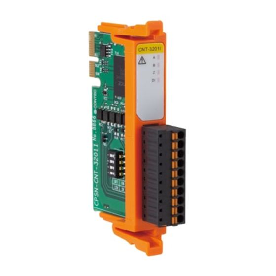
— — Product Nomenclature and Function CPSN-CNT-3201I Reference Manual (Hardware) 1. Nomenclature of Product Components Component names of the product are shown in the figure below. Name Function LED Indicator This indicates status of the product. Counter Input Connector This is a connector for counter input. (Use the 10-pin connector, included in the package) DIP Switch Used for voltage setting of external power supply. -
Page 18: Description Of Product Components
— — Product Nomenclature and Function CPSN-CNT-3201I Reference Manual (Hardware) 2. Description of Product Components Components such as connectors, switches are described. 1. LED Indicator Status of the product is indicated by ON/OFF and flashing of LED. The meaning of each LED is described below. Color and Description Color Display... -
Page 19: Counter Input Connector
— — Product Nomenclature and Function CPSN-CNT-3201I Reference Manual (Hardware) 2. Counter Input Connector This product has phase-A, phase-B, phase-Z, general-purpose input signals, and match signal output of counters. Use the 10-pin connector, included in the package to connect to external power. Connector type: DEGSON 15EDGKC-3.81-10P-13-00AH (or equivalent) Pin Assignment Pin No. -
Page 20: Dip Switch
— — Product Nomenclature and Function CPSN-CNT-3201I Reference Manual (Hardware) 3. DIP Switch A DIP Switch is used for external power supply voltage setting. By switching on or off, it can support both 5V and 12V external power. *The factory default of all switches are set to “OFF”. SW Number Description This switches phase-A input resistance. -
Page 21: Types And Operations Of Pulse Signals
— — Product Nomenclature and Function CPSN-CNT-3201I Reference Manual (Hardware) 3. Types and Operations of Pulse Signals 1. Types of Pulse Signals The following types of pulse signals (operation modes) can be set. 2-phase Input, Synchronous Clear, Multiply by 1 ... - Page 22 — — Product Nomenclature and Function CPSN-CNT-3201I Reference Manual (Hardware) Single-phase Input For a single-phase input, the count increments when an UP pulse is input and decremented when a DOWN pulse is input. The count remains unchanged if UP and DOWN pulses are input simultaneously. UP Pulse (Phase-A/UP) DOWN pulse...
-
Page 23: Multiplication Of Count Input
— — Product Nomenclature and Function CPSN-CNT-3201I Reference Manual (Hardware) 3. Multiplication of Count Input Setting the count input multiplication setting to two or four times enables you to fine-tune controlling. Example counting when count input multiplication is set During 2-Phase input When clockwise is specified When counterclockwise is specified... -
Page 24: Count Clear
— — Product Nomenclature and Function CPSN-CNT-3201I Reference Manual (Hardware) 4. Count Clear Example counting during synchronous clear If a counter is set for CW (clockwise) direction Up-count and phase-Z positive logic, within a low level input of phase-B, a high level signal of phase-Z input will reset the count value of this counter; after this phase-Z input signal goes to low level, the following rising edge of the phase-A signal will start the counting operation. - Page 25 — — Product Nomenclature and Function CPSN-CNT-3201I Reference Manual (Hardware) Phase Z/CLR Input Enable Frequency (Positive logic) Phase-Z is the signal to clear the counter to zero. The number of phase-Z inputs can be specified by software. Disable phase-Z input Phase-Z input - - - - - - - - - -...
-
Page 26: Other Functions
— — Product Nomenclature and Function CPSN-CNT-3201I Reference Manual (Hardware) 4. Other Functions 1. Compare Register Compare the count value of a corresponding channel with the compare register value. If these two values match, set status bit "EQ" to "0" (remains 0 as long as they are in agreement). This register can be set to any value from 0h to FFFFFFh. -
Page 27: One-Shot Pulse
— — Product Nomenclature and Function CPSN-CNT-3201I Reference Manual (Hardware) CAUTION All externally input signals (except for general-purpose input signals) are fetched through the digital filter into the internal counter. They are fetched after a delay of four set-sampling-cycle clocks. -
Page 28: Installation
Installation This section describes how to mount the product on a DIN rail, and to connect to an external device with a cable. — 28 —... -
Page 29: Install The Product
— — Installation CPSN-CNT-3201I Reference Manual (Hardware) 1. Install the Product 1. Installation Conditions Installation Orientation You can position the product in the orientation shown below. Other orientations may cause problems such as malfunctions due to inadequate heat dissipation. Vertical installation (Installation angle 0°) Vertical installation with an angle of 90°... - Page 30 — — Installation CPSN-CNT-3201I Reference Manual (Hardware) Horizontal installation Make sure to gain proper space between the product and devices that generate heat or exhaust air so that the ambient temperature stays in the range specified in the environment requirement. Also, the temperature range in the environment requirements varies depending on the installation orientation, so check the operating temperature range in "Specifications (Page 39)".
- Page 31 — — Installation CPSN-CNT-3201I Reference Manual (Hardware) CAUTION The product is an open-type device (a device designed to be housed inside other equipment) and must always be mounted inside a mechanical enclosure having enough strength. Note that although the ambient temperature is within the specified range, an operational ...
-
Page 32: Installing And Removing I/O Module And Blank Panels
— — Installation CPSN-CNT-3201I Reference Manual (Hardware) 2. Installing and Removing I/O Module and Blank Panels CAUTION Always confirm the PWR-LED is turned off before installing or removing the module. Installing Paying attention to the horizontal orientation of the I/O module, insert the resin groove into the rail of the CPU unit that has been installed on a DIN rail or that has been screwed into place, and then push the I/O module in until it clicks. - Page 33 — — Installation CPSN-CNT-3201I Reference Manual (Hardware) Removing Press in the hooks at the top and bottom of the I/O module, and then pull it toward you and out of the CPU unit that has been installed on a DIN rail or that has been screwed into place. —...
-
Page 34: Connecting To An External Device
— — Installation CPSN-CNT-3201I Reference Manual (Hardware) 2. Connecting to an External Device When connecting the product to an external device, use the supplied connector. When wiring the connector, strip off 8 mm ± 0.5 mm of the wire's covering, and then insert this stripped part into the connector's opening. -
Page 35: Cable Connection
— — Installation CPSN-CNT-3201I Reference Manual (Hardware) 3. Cable Connection 1. Counter Input Counter Input Cable Use the counter input cable described below. Cable Use copper wires that tolerate the temperature of 75°C and higher. Applicable wire AWG28 - 16 Cable Length The length differs depending on the actual use environment. - Page 36 — — Installation CPSN-CNT-3201I Reference Manual (Hardware) Connecting to an external device *The general-purpose input signals use the same circuit structure. CAUTION To use external power 5V, turn on all the DIP switches on the side of the product. ...
- Page 37 — — Installation CPSN-CNT-3201I Reference Manual (Hardware) Example Connection with a Rotary Encoder Example Connection with a Linear Scale One-shot Pulse Output Connection When the count value of each channel and the user set value match, the circuit outputs a matched signal for one shot (1 pulse).
-
Page 38: Appendix
Appendix This section lists the specifications and the physical dimensions of the product, and the details of model name. — 38 —... -
Page 39: Specifications
— — Appendix CPSN-CNT-3201I Reference Manual (Hardware) 1. Specifications Function Specifications Item Description Counter Input Number of Channels Count system Up/down counting Max. count FFFFFFFFH (binary data, 32-bit) Counter input type Opto-coupler isolated input (Compatible with current sink output) (Positive logic) Isolation Opto-coupler Isolation Voltage Resistance... - Page 40 — — Appendix CPSN-CNT-3201I Reference Manual (Hardware) Item Description Output rating 35VDC (Max.), 50mA (per 1 point) Residual Voltage with 0.5V or less Output ON Output signal width 0 - 104.45msec Output protection circuit Zener diode CMZB47 (Toshiba) or equivalence External power 5V - 12VDC±10% Connector...
- Page 41 — — Appendix CPSN-CNT-3201I Reference Manual (Hardware) Installation Environment Requirements Item Description Operating ambient temperature -20 - +60°C (Vertical installation) -20 to +55°C with a vertical installation at an angle of 90° to the left/right or with a horizontal installation. Operating ambient humidity 10 - 90%RH (No condensation) Non-operating ambient...
-
Page 42: Physical Dimensions
— — Appendix CPSN-CNT-3201I Reference Manual (Hardware) 2. Physical Dimensions Physical dimensions of CPSN-CNT-3201I. Physical dimensions of CPSN-CNT-3201I (with connector attached) — 42 —... -
Page 43: The Details Of Model Name
— — Appendix CPSN-CNT-3201I Reference Manual (Hardware) 3. The Details of Model Name Details of the model name are described below. Item Description Interface CNT Counter Resolution 32 bit Channel 1 Channel Isolation Bus Isolation — 43 —... -
Page 44: Optional Products
Optional Products This section lists optional items that can be used along with the product. — 44 —... -
Page 45: Optional Products
Fitting power supply 30W supply (Input: 100 - 240VAC, Output: 24VDC 1.3 A) CPS-PWD-90AW24-01 Fitting power supply 90W (Input: 100 - 240VAC, Output: 24VDC 3.8 A) Visit the Contec website for the latest optional products. https://www.contec.com/ Website — 45 —... -
Page 46: Customer Support And Inquiry
Customer Support and Inquiry CONTEC provides the following support services for you to use CONTEC products more efficiently and comfortably. — 46 —... -
Page 47: Services
— — Customer Support and Inquiry CPSN-CNT-3201I Reference Manual (Hardware) 1. Services CONTEC offers the useful information including product manuals that can be downloaded through the CONTEC website. Download https://www.contec.com/download/ You can download updated driver software, firmware, and differential manuals in several languages. Membership registration (myCONTEC) is required to use the services. - Page 48 — — Revision History CPSN-CNT-3201I Reference Manual (Hardware) Revision History MONTH YEAR Summary of Changes April 2020 The First Edition — 48 —...
- Page 49 3-9-31, Himesato, Nishiyodogawa-ku, Osaka 555-0025, Japan https://www.contec.com/ No part of this document may be copied or reproduced in any form by any means without prior written consent of CONTEC CO., LTD. CPSN-CNT-3201I Reference Manual (Hardware) NA07303 (LYYC032) 05152020_rev2 [04172020] May 2020 Edition...
Need help?
Do you have a question about the CONPROSYS nano CPSN-CNT-3201I and is the answer not in the manual?
Questions and answers