Table of Contents
Advertisement
Quick Links
N Series for USB
Reference Manual
Isolated Analog Input Unit (±10V Voltage Input)
AI-1608VIN-USB
Isolated Analog Input Unit (0 - 20mA Current Input)
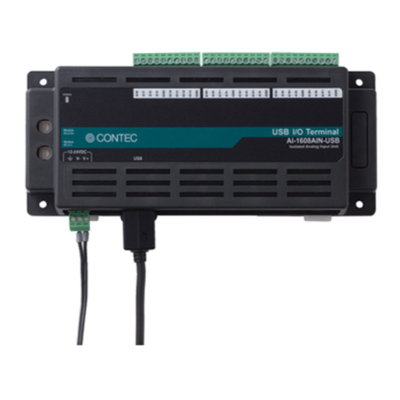
AI-1608AIN-USB
CONTENTS
Introduction .................................................................. 5
Safety Precautions .................................................... 13
Setup ............................................................................. 20
Installation ................................................................... 36
Software ....................................................................... 56
Function ....................................................................... 64
Appendix ...................................................................... 81
Customer Support and Inquiry ........................... 90
Advertisement
Table of Contents

Related Manuals for Contec AI-1608VIN-USB


Summary of Contents for Contec AI-1608VIN-USB
- Page 1 N Series for USB Reference Manual Isolated Analog Input Unit (±10V Voltage Input) AI-1608VIN-USB Isolated Analog Input Unit (0 - 20mA Current Input) AI-1608AIN-USB CONTENTS Introduction ..............5 Safety Precautions ............ 13 Setup ................20 Installation ..............36 Software ............... 56 Function ...............
-
Page 2: Table Of Contents
Table of Contents Introduction ............... 5 1. Related Manuals ..............................6 2. About the Product ..............................7 3. Features ..................................8 1. AI-1608VIN-USB ...............................8 2. AI-1608AIN-USB ...............................8 3. Common ................................8 4. Product Configuration List ..........................10 5. Support Software ..............................11 6. Optional Products ..............................12 Safety Precautions ............ - Page 3 1. Connecting an Interface Connector ...................... 45 2. Connecting Cable ............................46 3. Signal Layout on the Interface Connector ..................47 3. Connecting Analog Input Signal (AI-1608VIN-USB) ................48 1. Differential Input Connection ........................48 4. Connecting Analog Input Signal (AI-1608AIN-USB) ................50 1.
- Page 4 Table of Contents Appendix ................81 1. Hardware Specification ............................82 2. Physical Dimensions ............................86 1. Product ................................86 2. Physical dimensions of the supplied AC adapter (POA201-10-2) ........86 3. Circuit Block Diagram ............................87 4. Control Signal Timings ............................88 1.
-
Page 5: Introduction
Introduction This section provides necessary information of the product such as the outline, bundled items and manuals before actual use. — 5 —... -
Page 6: Related Manuals
— — Introduction AI-1608VIN-USB / AI-1608AIN-USB Reference Manual 1. Related Manuals The manuals related to the product are listed below. Read them as necessary along with this document. Must Read the Followings. Name Purpose Contents How to get Setup Guide... -
Page 7: About The Product
DIN rail. For AI-1608VIN-USB, 8 channels of 16-bit analog input, and digital input and output (4 channels respectively) are equipped, and these circuits are isolated from the computer. -
Page 8: Features
— — Introduction AI-1608VIN-USB / AI-1608AIN-USB Reference Manual 3. Features 1. AI-1608VIN-USB 8 channels of analog input (voltage input), and 4 channels of digital input and output respectively are contained with high accuracy Analog input (10μsec/ch, 16bit, 8ch), and digital input and output (Input: TTL level 4 channels, Output: Open-collector 4 channels) are equipped. - Page 9 — — Introduction AI-1608VIN-USB / AI-1608AIN-USB Reference Manual Compatible to USB1.1/USB2.0 Compatible to USB1.1/USB2.0 and capable to achieve high speed transfer at High Speed (480 Mbps) Diverse installations such as screw fastening, magnet, DIN rail are possible Installation on the floor / wall /ceiling is possible by screw fastening, magnet, rubber feet, etc.
-
Page 10: Product Configuration List
— — Introduction AI-1608VIN-USB / AI-1608AIN-USB Reference Manual 4. Product Configuration List The product consists of the items listed below. Check, with the following list, that your package is complete. If you discover damaged or missing items, contact your retailer. -
Page 11: Support Software
AI-1608VIN-USB / AI-1608AIN-USB Reference Manual 5. Support Software You can use CONTEC support software according to your purpose and development environment. For more details on the supported OS, applicable languages, or to download the latest version of software, visit the CONTEC Web site. -
Page 12: Optional Products
Magnet (Four Piece Set) The operating ambient temperature is 0 to 40 °C. It is the same adapter included in this package. The operating ambient temperature is -20 to 70 °C. Visit the CONTEC website for the latest optional products. https://www.contec.com/ Website... -
Page 13: Safety Precautions
Safety Precautions Understand the following definitions and precautions to use the product safely. Never fail to read them before using the product. — 13 —... -
Page 14: Safety Information
— — Safety Precautions AI-1608VIN-USB / AI-1608AIN-USB Reference Manual 1. Safety Information This document provides safety information using the following symbols to prevent accidents resulting in injury or death and the destruction of equipment and resources. Understand the meanings of these labels to operate the equipment safely. -
Page 15: Handling Precautions
Even when using the product continuously, be sure to read the manual in the CONTEC's website and understand the contents. Do not modify the product. CONTEC will bear no responsibility for any problems, etc., resulting from modifying the product. -
Page 16: Regarding "Ce Emc Directive Class A Notice
— — Safety Precautions AI-1608VIN-USB / AI-1608AIN-USB Reference Manual 1. Regarding “CE EMC Directive Class A Notice” The ferrite core must be installed on the AC adapter so that this product may suit the above- mentioned standard. See below for the type of the ferrite core. (Equivalent product can also be used). -
Page 17: Fcc Part15 Subpart B Class A
— — Safety Precautions AI-1608VIN-USB / AI-1608AIN-USB Reference Manual 2. FCC PART15 Subpart B Class A NOTE This equipment has been tested and found to comply with the limits for a Class A digital device, pursuant to part 15 of the FCC Rules. These limits are designed to provide reasonable protection against harmful interference when the equipment is operated in a commercial environment. -
Page 18: Environment
— — Safety Precautions AI-1608VIN-USB / AI-1608AIN-USB Reference Manual 3. Environment Use this product in the following environment. If used in an unauthorized environment, this product may overheat, malfunction, or cause a failure. Operating temperature -20 - 60ºC Humidity 10 - 90%RH (No condensation) -
Page 19: Storage
— — Safety Precautions AI-1608VIN-USB / AI-1608AIN-USB Reference Manual 5. Storage When storing this product, keep it in its original packing form. Put this product in the storage bag. Wrap it in the packing material, and then put it in the box. -
Page 20: Setup
Setup This section explains how to set up this product. — 20 —... -
Page 21: What Is Setup
— — Setup AI-1608VIN-USB / AI-1608AIN-USB Reference Manual 1. What is Setup? Setup means a series of steps to take before the product can be used. Different steps are required for driver software and hardware. The setup procedure varies with the OS or driver software used. -
Page 22: Driver Software Installation
CONTEC website. 1. Starting Up the Install Program Download the API-AIO(WDM) for USB from CONTEC website. Expand the downloaded file. Execute the installer in the expanded folder. As the installer differs depending on OS used, check the list below to execute. -
Page 23: Hardware Setting
— — Setup AI-1608VIN-USB / AI-1608AIN-USB Reference Manual 3. Hardware Setting This section describes how to set up the product and how to connect it to a PC. 1. Nomenclature of Product Components Component names of the product are shown in the figure below. -
Page 24: Led Indicator
— — Setup AI-1608VIN-USB / AI-1608AIN-USB Reference Manual 2. LED Indicator The product indicates its operation state by means of light emitting diodes. The LED indicates as listed below. List of Status LED Functions Function Color Display Description The power is supplied to this product. -
Page 25: Power Supply Connector
— — Setup AI-1608VIN-USB / AI-1608AIN-USB Reference Manual 5. Power Supply Connector This product must be connected by using the 12-24VDC power supply (in a self-powered state). Connect the external power supply to the power supply connector. Pin Assignment Mark... - Page 26 — — Setup AI-1608VIN-USB / AI-1608AIN-USB Reference Manual About a power rise Input voltage range: 12 - 24VDC plus or minus 10 percentages. Use the power that can rise in the input voltage range of 11.4VDC or greater within 10ms. Other power supply may cause a damage to the product or an accident.
-
Page 27: Hardware Installation
— — Setup AI-1608VIN-USB / AI-1608AIN-USB Reference Manual 4. Hardware installation Under Windows, the peripherals need to be recognized by the OS. This is called hardware installation. When using multiple products, install one product at a time. Complete the setup of the product before starting to install the next one. - Page 28 — — Setup AI-1608VIN-USB / AI-1608AIN-USB Reference Manual CAUTION Connect the 12 - 24VDC power supply (such as the AC adapter) to the product first, then connect to a PC. Do not turn on or off during the operation. When unplugging, unplug the USB cable first, then disconnect the external power supply.
-
Page 29: Connecting The Product
— — Setup AI-1608VIN-USB / AI-1608AIN-USB Reference Manual 2. Connecting the Product Turn on the power to the PC before connecting this product. When the PC has been up and running, connect the product to a USB port in the PC. *1 Connect the product to a USB port in the PC. -
Page 30: Driver Software Initialization
For other than Windows 10, From the [Control Panel], select the [Hardware and Sounds] or the [System] and then select the [Device Manager]. The installed hardware appears under the CONTEC Devices node. Open the CONTEC Devices node and select the device you want to setup. Click the [Properties]. — 30 —... - Page 31 — — Setup AI-1608VIN-USB / AI-1608AIN-USB Reference Manual The property page for the device opens. Enter the device name in the Common Settings tab page and then click the [OK]. The device name you set here is used later when programming.
-
Page 32: Operation Check
— — Setup AI-1608VIN-USB / AI-1608AIN-USB Reference Manual 6. Operation Check You must make sure that this product and driver software operate properly. By taking this step, you can be certain that this product has been set up appropriately. 1. Check Method Connect the product to an external target device to test the communication and check the execution environment. - Page 33 — — Setup AI-1608VIN-USB / AI-1608AIN-USB Reference Manual Checking Functions The main dialog box of the Diagnosis Program appears. You can check the current operation states of the product in the following boxes: Analog input Select the input channel and input type from the lists.
- Page 34 — — Setup AI-1608VIN-USB / AI-1608AIN-USB Reference Manual Diagnosis Report Clicking on [Diagnosis] displays detailed data including product settings and the diagnosis results while saving them in text format. The diagnosis program performs the presence or absence of the product, driver file test, the board setting test, and so on.
-
Page 35: Setup Troubleshooting
— — Setup AI-1608VIN-USB / AI-1608AIN-USB Reference Manual 7. Setup Troubleshooting 1. Examples and Solution The diagnostic program works properly but the application program does not. The diagnostic program uses the API-AIO(WDM) for USB functions. If the diagnostic program works properly, other applications should also work properly. -
Page 36: Installation
Installation This section describes how to mount the product on a DIN rail or on the wall, and to connect to an external device with a cable. — 36 —... -
Page 37: Installing The Product
— — Installation AI-1608VIN-USB / AI-1608AIN-USB Reference Manual 1. Installing the Product 1. Installation Conditions Installation Orientation It is possible to mount it in the orientations shown in the following figure. Other orientations would cause problems in usage, such as inadequate heat dissipation. - Page 38 — — Installation AI-1608VIN-USB / AI-1608AIN-USB Reference Manual Screws / magnet fixation Vertical installation CAUTION The product cannot be installed on the ceiling with magnets. — 38 —...
- Page 39 — — Installation AI-1608VIN-USB / AI-1608AIN-USB Reference Manual Spacing between the system unit and any surrounding objects Secure a distance of at least 50mm between the top of the product (single use) and any surrounding objects. Do not locate the product in a fully enclosed housing.
-
Page 40: Mounting On/Removing From A Din Rail
— — Installation AI-1608VIN-USB / AI-1608AIN-USB Reference Manual 2. Mounting on/Removing from a DIN Rail How to Mount Pull down the hooks to unlock. If the hooks are stuck, use a slotted screwdriver to unlock. (1). Hang the product on the upper part of the DIN rail. - Page 41 — — Installation AI-1608VIN-USB / AI-1608AIN-USB Reference Manual How to Remove Pull down the hooks to unlock. If the hooks are stuck, use a slotted screwdriver to unlock. (1). With the hooks unlocked, pull the lower part of the product toward you.
-
Page 42: Desktop Installation
— — Installation AI-1608VIN-USB / AI-1608AIN-USB Reference Manual 3. Desktop Installation Using the rubber feet When required to mount the product on the desktop, mount it horizontally on a sturdy platform. The rubber feet can be mounted in their mounting holes as shown in the following figure. -
Page 43: Installation Using The Magnet
— — Installation AI-1608VIN-USB / AI-1608AIN-USB Reference Manual 5. Installation Using the Magnet Attaching the magnet (optional) with the product makes it easy to mount or remove the product on or from a metal surface such as steel desk or partition. - Page 44 — — Installation AI-1608VIN-USB / AI-1608AIN-USB Reference Manual Mounting onto the steel wall Mount the product directly onto the steel wall. Pull it gently after mounting to confirm that it will not drop off from the body. — 44 —...
-
Page 45: Connecting To An External Device
— — Installation AI-1608VIN-USB / AI-1608AIN-USB Reference Manual 2. Connecting to an External Device 1. Connecting an Interface Connector Use the supplied interface connector (plug connector) to connect the product to an external device. The following example describes how to make the connecting cable with the interface connector (connector plug). -
Page 46: Connecting Cable
Use the analog input cable listed below. Applicable wire AWG28 - 16 Cable Length For AI-1608VIN-USB : Within 1.5 meters * If higher accuracy is required, the cable length should be 0.5 meters or shorter. For AI-1608AIN-USB : Within 20 meters Digital I/O Cable Use the digital I/O cable listed below. -
Page 47: Signal Layout On The Interface Connector
— — Installation AI-1608VIN-USB / AI-1608AIN-USB Reference Manual 3. Signal Layout on the Interface Connector The product can be connected to an external device using three 10-pin connectors included in the package. Layout on the Interface Connector DI 00 -- DI 03 Digital input pins. -
Page 48: Connecting Analog Input Signal (Ai-1608Vin-Usb)
— — Installation AI-1608VIN-USB / AI-1608AIN-USB Reference Manual 3. Connecting Analog Input Signal (AI-1608VIN-USB) Here are examples on how to connect analog input signals of interface connector with flat cable or shield cable. 1. Differential Input Connection Connection example with flat cable The following figure shows an example of flat cable connection. - Page 49 — — Installation AI-1608VIN-USB / AI-1608AIN-USB Reference Manual An input analog signal that inputs to the [+] input or the [-] input should not exceed the maximum input voltage and current listed in the “Function Specifications (Page82)”. The product may be damaged if the maximum voltage or current is exceeded.
-
Page 50: Connecting Analog Input Signal (Ai-1608Ain-Usb)
— — Installation AI-1608VIN-USB / AI-1608AIN-USB Reference Manual 4. Connecting Analog Input Signal (AI-1608AIN-USB) Here are examples on how to connect analog input signals of interface connector with flat cable or shield cable. 1. Connection Example of Current Input Connecting with two-terminal current output (Flat Cable) The following shows an example of flat cable connection with two-terminal current output. - Page 51 — — Installation AI-1608VIN-USB / AI-1608AIN-USB Reference Manual Connecting with current sink output (Flat Cable) The following shows an example of flat cable connection with current sink output. Connect the [+] input of analog input channel of the interface connector to the positive side of the current source, and the [-] input to the output terminal of the current source respectively.
- Page 52 — — Installation AI-1608VIN-USB / AI-1608AIN-USB Reference Manual CAUTION If the signal source contains over 1 MHz signals, the signal may affect the cross-talk noise between channels. When the analog ground is not connected, the conversion data is not determined.
-
Page 53: Connecting Digital I/O Signals
— — Installation AI-1608VIN-USB / AI-1608AIN-USB Reference Manual 5. Connecting Digital I/O Signals Digital I/O signals can be used as control I/O signals (external trigger input signals, sampling clock input signals, etc.). The following section shows examples of how to connect signals. -
Page 54: Example Connection With Switch
— — Installation AI-1608VIN-USB / AI-1608AIN-USB Reference Manual 2. Example Connection with switch When switch is “ON”, the corresponding bit is “1”. When switch is “OFF” in contrast, the corresponding bit is “0”. 3. Output Circuit The following is an output circuit of the interface (connector) part. - Page 55 — — Installation AI-1608VIN-USB / AI-1608AIN-USB Reference Manual Example Connection with LED When “1” is output to a relevant bit, the corresponding LED comes on. When “0” is output to the bit, in contrast, the LED goes out. — 55 —...
-
Page 56: Software
Software This section describes analog input and output driver for Windows developed by CONTEC and CONTEC Device Utility. — 56 —... -
Page 57: Analog I/O Driver For Windows
From “Start” menu on Windows task bar, click on [CONTEC API-USBP(WDM)]-[API-USBP(W32) Help] to display help information. If this link cannot be found, go to the “Start” menu on Windows task bar, click “CONTEC API- USBP(WDM)” – “API-AIO(WDM) “ – “API-AIO(WDM) HELP”. -
Page 58: Running A Sample Program
Software AI-1608VIN-USB / AI-1608AIN-USB Reference Manual 3. Running a Sample Program From the Start Menu on the Windows taskbar, go to “Programs” - “CONTEC API-AIO(WDM) for API-USBP(WDM)” and select the sample programs. Sample Programs - Examples Perform single analog input from specified channel [SingleAi] ... - Page 59 — — Software AI-1608VIN-USB / AI-1608AIN-USB Reference Manual Analog Output Measurement Tool It is an analog output measurement utility to carry out infinity sample in the FIFO memory. Once the conversion data of memory accumulates to a certain quantity, the event occurs and new output data is added.
-
Page 60: Uninstalling The Driver Software
Uninstall of Device Driver Use [Control Panel] - [Programs and Features] to uninstall the development environment. Select [Windows driver package - CONTEC (Caio) Contec] and then click [Uninstall/Change]. Uninstall the Development Environment Use [Control Panel] - [Programs and Features] to uninstall the development environment. -
Page 61: Returning To Initial State
Then, unplug the external power supply (such as the AC adapter) for self-power as well. Uninstall two of the following programs listed from Control Panel in order. “Windows Driver Package - CONTEC (caio) Contec” “CONTEC API-AIO(WDM) driver” Reboot OS, and install software and hardware again. -
Page 62: Contec Device Utility
Software AI-1608VIN-USB / AI-1608AIN-USB Reference Manual 2. CONTEC Device Utility CONTEC Device Utility is utility software to setup the CONTEC's measuring control device. Use this software to update firmware of the product. 1. Updating Firmware Firmware is namely software which is embedded in the product. Up-to-date firmware (update file) will be supplied in the CONTEC website when function upgrades and so on. - Page 63 — — Software AI-1608VIN-USB / AI-1608AIN-USB Reference Manual Start up the Utility. Start up CONTEC Device Utility. (The utility can be found in Utility folder of API-AIO(WDM) for USB driver.) Write firmware. Select the product from the list, and perform updating firmware.
-
Page 64: Function
Function This section describes the features achieved by combining hardware and driver functions. — 64 —... -
Page 65: Analog Input Function
— — Function AI-1608VIN-USB / AI-1608AIN-USB Reference Manual 1. Analog Input Function The product converts analog signals to digital data according to the resolution and stores it in memory. You can set a variety of conditions for analog input, including the input channel, sampling period, and sampling start/stop conditions. -
Page 66: Setting The Conversion Conditions
— — Function AI-1608VIN-USB / AI-1608AIN-USB Reference Manual 1. Setting the Conversion Conditions First, set the conditions for executing analog input. Resolution “Resolution” signifies the number of bits used by an analog input device to represent analog signals. The higher the resolution, the more finely the voltage range is segmented, allowing the device to convert analog values to digital equivalents more precisely. - Page 67 — — Function AI-1608VIN-USB / AI-1608AIN-USB Reference Manual Channel “Channel” represents each channel No. of analog input signal. For channel numbers, see “Connecting an Interface Connector(Page45)”. Any number of analog inputs can be performed by setting up channels with software.
- Page 68 — — Function AI-1608VIN-USB / AI-1608AIN-USB Reference Manual Data Transfer Method A device buffer mode is available, which uses the device's or driver's conversion data storage memory. When conversion starts, data is saved in the device buffer (memory on the device itself or in the driver).
- Page 69 — — Function AI-1608VIN-USB / AI-1608AIN-USB Reference Manual Memory Format You can select memory format by software. FIFO format In the FIFO (First In First Out) format, conversion data are read from memory in the same order in which they were written to the memory. Conversion data are fed out of the memory sequentially, where the oldest one is always read from the memory.
- Page 70 — — Function AI-1608VIN-USB / AI-1608AIN-USB Reference Manual Clock The sampling clock controls the sampling frequency. You can select either the internal sampling clock, or external sampling clock. Internal sampling clock The clock signal from the installed clock generator is used.
- Page 71 — — Function AI-1608VIN-USB / AI-1608AIN-USB Reference Manual The above sketch shows that the level comparison condition is satisfied in the falling direction. The start condition is satisfied when the analog signal at the specified channel passes the comparison level in the falling direction. Conversion data are stored to memory, starting with those at solid dots.
- Page 72 — — Function AI-1608VIN-USB / AI-1608AIN-USB Reference Manual Stop Condition The condition for controlling the stop of sampling can be selected from among the last sampling count, conversion data comparison, an external trigger, and software abort. The product stops sampling whenever an error occurs irrespective of the stop condition setting.
-
Page 73: Starting/Stopping Operation
— — Function AI-1608VIN-USB / AI-1608AIN-USB Reference Manual External trigger The product starts waiting for an external control signal as soon as the operation start command is output. Sampling stops when the specified edge (rising edge or falling edge) is input from the external control signal. -
Page 74: Monitoring The Status And Acquiring Data
— — Function AI-1608VIN-USB / AI-1608AIN-USB Reference Manual 3. Monitoring the Status and Acquiring Data Software commands are used to monitor the operation status of the device and to acquire conversion data from memory. Status monitoring and data acquisition can be performed even during sampling. - Page 75 — — Function AI-1608VIN-USB / AI-1608AIN-USB Reference Manual AD conversion error If the “device operating” status remains ON (without terminating conversion) for an extended period of time, the driver regards that state as an operation error and sets this status to ON. This error stops sampling.
- Page 76 — — Function AI-1608VIN-USB / AI-1608AIN-USB Reference Manual Data acquisition in RING format When ring memory is used, data is read always with respect to the current input data write position. The following sketch shows an image of data acquisition in ring format.
- Page 77 — — Function AI-1608VIN-USB / AI-1608AIN-USB Reference Manual Conversion data The following equation represents the relation between conversion data and voltage. Voltage or Current = Conversion data x (Max. range value - Min. range value) ÷ Resolution + Min.
-
Page 78: Reset
— — Function AI-1608VIN-USB / AI-1608AIN-USB Reference Manual 4. Reset Various states can be reset by executing the following reset commands: Status This command resets the sampling clock error status and AD conversion error status. Memory This can only be used when the transfer mode is set to device buffer mode. -
Page 79: Digital Input Function
— — Function AI-1608VIN-USB / AI-1608AIN-USB Reference Manual 2. Digital Input Function Input bit Individual digital input points are called input bits. When the number of input points of a device is 4, the bits are determined as bit 0 - bit 3. -
Page 80: Digital Output Function
— — Function AI-1608VIN-USB / AI-1608AIN-USB Reference Manual 3. Digital Output Function Output bit Individual digital output points are called output bits. When the number of output points of a device is 4, the bits are determined as bit 0 - bit 3. -
Page 81: Appendix
Appendix This section lists the specifications and the physical dimensions of the product. — 81 —... -
Page 82: Hardware Specification
— — Appendix AI-1608VIN-USB / AI-1608AIN-USB Reference Manual 1. Hardware Specification Function Specifications Item AI-1608VIN-USB AI-1608AIN-USB Analog input Isolated specification Bus-Isolated Input type Differential Input Input channel Input range Voltage: Bipolar ±10V Current: 0 - 20mA Maximum input rating 30mA ±15V... - Page 83 — — Appendix AI-1608VIN-USB / AI-1608AIN-USB Reference Manual Item AI-1608VIN-USB AI-1608AIN-USB Physical dimensions (mm) 188.0(W)×78.0(D)×30.5(H) (No projection included) Weight 250g (Not including the USB cable or attachment) The length of cable (supplied) USB cable(Type A - mini-B type) 1.8m *1 The non-linearity error means an error of approximately ±0.1% occurs over the maximum range at -20°C and 60°C ambient temperature.
- Page 84 — — Appendix AI-1608VIN-USB / AI-1608AIN-USB Reference Manual Installation Environment Requirements Item AI-1608VIN-USB AI-1608AIN-USB Operating ambient temperature -20 - +60°C *8 Operating ambient humidity 10 - 90%RH (No condensation) Floating dust particles Not to be excessive Corrosive gases None Line-noise Line noise AC Line/±2kV...
- Page 85 — — Appendix AI-1608VIN-USB / AI-1608AIN-USB Reference Manual AC adapter environmental condition (environmental specification) Item Specifications Input voltage range 90 - 264VAC Rated input current 300mA Number of frequency 50 - 60Hz Rated output voltage 12.0VDC Rated output current 1.0A (Max.) Physical dimensions (mm) 47.5(W)x75(D)x27.3(H) (No protrusions)
-
Page 86: Physical Dimensions
— — Appendix AI-1608VIN-USB / AI-1608AIN-USB Reference Manual 2. Physical Dimensions 1. Product 2. Physical dimensions of the supplied AC adapter (POA201-10-2) — 86 —... -
Page 87: Circuit Block Diagram
— — Appendix AI-1608VIN-USB / AI-1608AIN-USB Reference Manual 3. Circuit Block Diagram — 87 —... -
Page 88: Control Signal Timings
— — Appendix AI-1608VIN-USB / AI-1608AIN-USB Reference Manual 4. Control Signal Timings 1. Control Signal Timings for Analog Input Figures and a Table below show the control signal timings for the analog input function. Timing Chart of External Sampling Clock... -
Page 89: About Calibration
— — Appendix AI-1608VIN-USB / AI-1608AIN-USB Reference Manual 5. About Calibration Although this product is calibrated before shipping, you can use the calibration program to calibrate analog input yourself. Starting the calibration program Click the [Calibration] button on the property page for the device to start the calibration program. -
Page 90: Customer Support And Inquiry
Customer Support and Inquiry CONTEC provides the following support services for you to use CONTEC products more efficiently and comfortably. — 90 —... -
Page 91: Services
— — Customer Support and Inquiry AI-1608VIN-USB / AI-1608AIN-USB Reference Manual 1. Services CONTEC offers the useful information including product manuals that can be downloaded through the CONTEC website. Download https://www.contec.com/download/ You can download updated driver software, firmware, and differential manuals in several languages. - Page 92 — — Customer Support and Inquiry AI-1608VIN-USB / AI-1608AIN-USB Reference Manual Revision History MONTH YEAR Summary of Changes March 2019 The First Edition. May, 2019 Support software and optional products are added. — 92 —...
- Page 93 3-9-31, Himesato, Nishiyodogawa-ku, Osaka 555-0025, Japan https://www.contec.com/ No part of this document may be copied or reproduced in any form by any means without prior written consent of CONTEC CO., LTD. AI-1608VIN-USB / AI-1608AIN-USB Reference Manual NA06370 (LYWF582) 05102019_rev2 [03062019] May 2019 Edition...
Need help?
Do you have a question about the AI-1608VIN-USB and is the answer not in the manual?
Questions and answers