
Related Manuals for Contec COM-4CN-USB


Summary of Contents for Contec COM-4CN-USB
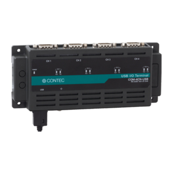
- Page 1 PC-HELPER N Series for USB RS-232C 4ch Serial I/O Unit COM-4CN-USB User’s Guide CONTEC CO., LTD.
- Page 2 Check Your Package Thank you for purchasing the CONTEC product. The product consists of the items listed below. Check, with the following list, that your package is complete. If you discover damaged or missing items, contact your retailer. Product Configuration List - Product [COM-4CN-USB] …1...
-
Page 3: Copyright
No part of this document may be copied or reproduced in any form by any means without prior written consent of CONTEC CO., LTD. CONTEC CO., LTD. makes no commitment to update or keep current the information contained in this document. The information in this document is subject to change without notice. -
Page 4: Table Of Contents
Setting with the Found New Hardware Wizard ................14 Step 3 Initializing the Software ......................15 Step 4 Operation check ........................16 Check Method ..........................16 Using the Diagnostic Program for Serial Communications Port ..........17 If Setup fails to be performed normally ..................... 18 COM-4CN-USB... - Page 5 XON/XOFF Automatic control function ..................29 Setting the Baud Rate ......................... 30 ABOUT SOFTWARE About standard COM driver software ....................31 About Sample programs ........................31 Uninstalling the Driver Libraries ....................... 32 ABOUT HARDWARE Hardware specification ........................33 Physical dimensions ........................... 34 COM-4CN-USB...
-
Page 6: Before Using The Product
Installation on the floor / wall /ceiling is possible by screw fastening, magnet (option), rubber feet, etc. In addition, DIN rail mounting mechanism is equipped as standard with the product, making it easy to install the product within the panel or the device. COM-4CN-USB... -
Page 7: Support Software
Visual Basic communication control (MSComm). Supports the communication class of .NET Framework (SerialPort class). For more details on the supported OS, applicable language and new information, please visit the CONTEC’s Web site. Accessories (Option) Magnets for installation (For piece Set) CPS-MAG01-4 * Check the CONTEC’s Web site for more information on these options. -
Page 8: Customer Support
You can download updated driver software and differential files as well as sample programs available in several languages. Note! For product information Contact your retailer if you have any technical question about a CONTEC product or need its price, delivery time, or estimate information. Limited One-Year Warranty CONTEC products are warranted by CONTEC CO., LTD. -
Page 9: Safety Precautions
Even when using this product continuously, be sure to read the manual and understand the contents. Do not modify this product. CONTEC will bear no responsibility for any problems, etc., resulting from modifying this product. Regardless of the foregoing statements, CONTEC is not liable for any damages whatsoever (including damages for loss of business profits) arising out of the use or inability to use this CONTEC product or the information contained herein. - Page 10 The ferrite core must be installed in interface connecting cable so that this product may suit the above-mentioned standard. Name Maker Turn Quantity Installation Site E04SR200935A SEIWA on USB cable at product Image diagram Ferrite core Cable TURN : 1 TURN : 2 TURN : 4 TURN : 3 COM-4CN-USB...
- Page 11 FCC WARNING Changes or modifications not expressly approved by the party responsible for compliance could void the user's authority to operate the equipment. EN55032 Class A Notice Warning: Operation of this equipment in a residential environment could cause radio interference. COM-4CN-USB...
-
Page 12: Environment
Floating dust particles Not to be excessive Inspection Inspect the product periodically as follows to use it safely. USB I/OTerminal COM-4CN-USB RS-232C 4ch I/O Unit - Check that the connector has no dust or foreign matter adhering. CAUTION Be certain that the ventilation holes of this product are not closed and also no dust or foreign matter is adhered to them. - Page 13 1. Before Using the Product COM-4CN-USB...
-
Page 14: Setup
“COM Setup Disk”. You can use the diagnosis program later to check whether the software and hardware function normally. Step 1 Installing the Software Step 2 Setting the Hardware Step 3 Initializing the Software Step 4 Operation Check COM-4CN-USB... -
Page 15: Step 1 Installing The Software
2. Setup Step 1 Installing the Software Install software. Run [\USB\COM-4CN-USB\Setup.exe] from the bundled disk. (1) The screens below show the installation.Click [next]. (2) Accept the license agreement, then click [Next>]. (3) The setup is completed. COM-4CN-USB... -
Page 16: Step 2 Installing The Hardware
If you are using more than one product, be sure to complete the first installation, then install the next one. Name of each parts Interface connector LED indicator USB I/O Terminal COM-4CN-USB RS-232C 4ch I/O Unit USB cable attachment Interface connector USB Type A For PC USB2.0 (mini-B type) -
Page 17: Component Functions
The USB cable attachment cannot be used excluding an attached cable. When the USB cable attachment is being used, do not perform removing and connecting the USB cable on the product side repeatedly. This may damage the USB cable attachment or yourself. COM-4CN-USB... - Page 18 It may cause a trouble in recognizing and operating the device according to the kind of USB hub. It is newly recognized as another COM port number when replacing the universal serial bus port and putting on the USB hub and substituting it. COM-4CN-USB...
-
Page 19: Setting With The Found New Hardware Wizard
(2) When the model name of hardware is displayed, select “Install the software automatically [Recommended]” and then click on the “Next” button. * The name of the connected product will be displayed. COM-4CN-USB The device is automatically installed, and processing is completed. You have now finished installing the initial setting of Hardware. COM-4CN-USB... -
Page 20: Step 3 Initializing The Software
* The name of the connected product will be displayed. COM-4CN-USB (2) Check that the new COM ports are displayed in the [Ports] folder. (3) If you wish to change a port number, open the properties page for the port and click the [Advanced…] button under [Port Settings]. -
Page 21: Step 4 Operation Check
Obtain an RS-232C cross cable. If you do not have a cross cable, you can use a switch on the product to perform testing of a single COM port using loopback communications. See the figure below for the switch settings. Switch setting for using a cross cable <9pin> <25pin> Unit side Unit side COM-4CN-USB... -
Page 22: Using The Diagnostic Program For Serial Communications Port
[Device1] and [Device2]. When performing loopback communications on a single COM port, set the same port number in both [Device 1] and [Device 2]. Communication Settings: Specify the [Bits / Second], [Data bits] and other settings you wish to use. COM-4CN-USB... -
Page 23: If Setup Fails To Be Performed Normally
Click the [Start] button to start the test using the specified conditions. View test result The test result is displayed in the [Message] window. A successful completion message appears if the test completed OK. If Setup fails to be performed normally Contact your retailer. COM-4CN-USB... -
Page 24: Installation And Connecting With External Devices
(2) Hook the product on the upper part of the DIN rail, and press it to the lower part of to the DIN rail. Figure 3.1. Mounting on a DIN Rail < 2 / 3 > (3) Push the fixing hooks up with a slotted screwdriver to lock. Figure 3.1. Mounting on a DIN Rail < 3 / 3 > COM-4CN-USB... - Page 25 Figure 3.2. Removing the product from the DIN rail < 2 / 3 > (3) By lifting this product, you can easily remove it from the DIN rail. Figure 3.2. Removing the product from the DIN rail < 3 / 3 > COM-4CN-USB...
-
Page 26: Desktop Installation
The rubber feet can be mounted in their mounting holes as shown in the following figure. Figure 3.3. Mounting the rubber feet Wall Installation Appropriate screws (fit into φ3.5 hole) are required to install the product on the wall. The commercial screws can be purchased individually. Screw Figure 3.4. Wall Installation COM-4CN-USB... -
Page 27: Installation Using The Magnet
Figure 3.5. Mounting the magnet To remove the magnet, slide the magnet in the direction of arrow 1 as shown in the following figure, and then lift it out in the direction of arrow 2. Figure 3.6. Removing the magnet COM-4CN-USB... -
Page 28: Steel Wall Installation
(1) Align the solderless terminal with the screw hole, then tighten the supplied external toothed lock screw (M4 x 5). Figure 3.8. Attaching the FG CAUTION Screw holes may be damaged if screws are tightened with a torque greater than the specified torque.The specified tightening torque is 5 - 6kgf⋅cm. COM-4CN-USB... -
Page 29: Installation Conditions
Screws / magnet fixation Vertical installation Horizontal installation Installation on a ceiling Figure 3.10. Screws / magnet fixation CAUTION When using the product in a high temperature environment, cool it by blowing air even when the temperature is within the specified range. COM-4CN-USB... - Page 30 Secure a distance of at least 50mm between the top of the main product (single use) and any surrounding objects. Do not locate the product in a fully enclosed housing. 50mm 50mm or more or more Figure 3.11. Spacing between the product and any surrounding objects COM-4CN-USB...
-
Page 31: Connection Method
Thumb screw: UNC#4-40(inch screw) - Connector used DELC-J9PAF-20L9E equivalent [mfd. by JAE,Male] - Applicable connectors 17JE-13090-02(D8C) [mfd. by DDK, Female] Figure 3.12 Interface Connector Connector Pin Assignment Pin Assignments of COM-4CN-USB Interface Connector Figure 3.13 Pin Assignments of Interface Connector COM-4CN-USB... -
Page 32: Types Of Cable And Example Connections
Figure 3.14. Example Connection to a Modem (Straight cable) Figure 3.15. Example Connection to a PC (Cross cable) Figure 3.16. Example Connection to a Device COM-4CN-USB... - Page 33 3. Installation and connecting with external devices COM-4CN-USB...
-
Page 34: Function
The buffers operate as FIFO buffers and help reduce the load on the CPU for high-speed communications or system operation. XON/XOFF Automatic control function This converter is controlled by the software flow automatically on hardware. Therefore, it is not necessary to observe with software like a current application, and the best system can be constructed. COM-4CN-USB... -
Page 35: Setting The Baud Rate
Table 4.1. Baud Rate Generator Programming Table Output baud rate [bps] Setup error (%) 1200 0.0025 1800 2000 2400 0.0025 3600 4800 0.0100 7200 9600 0.0100 14400 19200 0.0400 28800 38400 0.0400 57600 76800 0.1603 115200 0.1603 153600 0.1603 230400 0.1603 460800 921600 0.1603 COM-4CN-USB... -
Page 36: About Software
About Sample programs The sample program \Samples is included in the bundled disk. Use this for reference and testing when developing software. Example of sample Transmit/Receive sample Sends data entered from the keyboard and displays received data on the screen. COM-4CN-USB... -
Page 37: Uninstalling The Driver Libraries
5. About Software Uninstalling the Driver Libraries < Uninstalling the Driver Libraries > Uninstall the driver from “My computer”-“Control Panel”-“Program and Features”. Select [Windows Deriver Package - CONTEC CO.,LTD (xrusbser) Ports] and [Windows Driver Package - CONTEC USB] to delete. COM-4CN-USB... -
Page 38: About Hardware
Data transmission at high speed may not be performed normally depending on the environment including the type of status of connected material of cable and environment. This depends on the PC environment used (OS and USB host controller). To suppress the heating, ensure that there are spaces for ventilation (about 5cm) around this product. COM-4CN-USB... -
Page 39: Physical Dimensions
6. About Hardware Physical dimensions USB I/O T erminal COM-4CN-USB R S-232C 4ch I/O Unit (154) [mm] Figure 6.1. Physical dimensions COM-4CN-USB... - Page 41 CONTEC CO., LTD. June 2018 Edition 3-9-31, Himesato, Nishiyodogawa-ku, Osaka 555-0025, Japan https://www.contec.com/ No part of this document may be copied or reproduced in any form by any means without prior written consent of CONTEC CO., LTD. [06052018] [10252017] Management No. NA05916 [06052018_rev2] Parts No.
Need help?
Do you have a question about the COM-4CN-USB and is the answer not in the manual?
Questions and answers