Table of Contents

Related Manuals for Johnson Controls YORK


Summary of Contents for Johnson Controls YORK
- Page 1 Centrifugal Liquid Chillers Field Reassembly for Form 2, 3, and 7 Shipment, Model YD (Style D) (Cooling Only) with OptiView Control Center Installation Guide Form Number: 160.79-N1 (320) Issue Date: 2020-03-31 Supersedes: 160.79-N1 (118)
-
Page 3: Table Of Contents
Contents General safety guidelines......................3 Safety symbols............................. 3 Changeability of this document......................4 Associated literature........................... 4 Nomenclature............................6 Shipping............................7 General..............................7 Field assembled units only......................... 7 Shipment............................... 8 Inspection – damage – shortage....................... 9 Chiller data plate..........................9 Long-term storage..........................10 Rigging.............................. - Page 4 Installing optional spring isolators....................37 Piping connections..........................38 Evaporator and condenser water piping..................38 Refrigerant relief piping........................40 Unit piping............................41 Control panel positioning......................... 41 Control wiring............................ 42 Power wiring............................42 Insulation............................43 Installation checklist and request for start-up................44 Reassembly............................
-
Page 5: General Safety Guidelines
General safety guidelines Important: Read before proceeding. This equipment is a relatively complicated apparatus. During rigging, installation, operation, maintenance, or service, individuals may be exposed to certain components or conditions including, but not limited to: heavy objects, refrigerants, materials under pressure, rotating components, and both high and low voltage. -
Page 6: Changeability Of This Document
All wiring must be in accordance with Johnson Controls’ published specifications and must be performed only by a qualified electrician. Johnson Controls will NOT be responsible for damage/problems resulting from improper connections to the controls or application of improper control signals. - Page 7 Description Form number Wiring Diagram - Field Connections YD Style D Optiview Control Center with 160.79-PW6 Unit Mounted Low Voltage SSS Wiring Diagram - Field Connections YD Style D Optiview Control Center with 160.79-PW7 Unit Mounted Low Voltage VSD Wiring Diagram - Field Connections YD Style D Optiview Control Center with 160.79-PW8 Unit Mounted Medium Voltage SSS Wiring Diagram - Field Connections YD Style D Optiview Control Center with...
-
Page 8: Nomenclature
Nomenclature Centrifugal Liquid Chillers... -
Page 9: Shipping
Continental United States. CAUTION The Johnson Controls Warranty may be voided if the following restrictions are not adhered to. 1. Do not open any valves or connections under any circumstances because such action will result in loss of the factory nitrogen charge. -
Page 10: Shipment
• Miscellaneous material – vibration isolation pads (or optional spring isolators and brackets) will ship loss. Note: Units shipped dismantled must be reassembled by, or under the supervision of, a Johnson Controls representative. Form 3 - Drivelines separate from shells • H9, K1, and K2 liquid chilling units. -
Page 11: Inspection - Damage - Shortage
Report any damage or signs of possible damage to the transportation company immediately for their inspection. Note: Johnson Controls will not be responsible for any damage in shipment or at job site or loss of parts. Refer to Shipping Damage Claims (Form 50.15-NM). -
Page 12: Long-Term Storage
• Water passes • Refrigerant charge • Serial numbers • Motor power characteristics and connection diagrams Additional information may be found on the motor data plates. This information should be included when contacting the factory on any problem relating to the motor. Long-term storage To protect the waterbox of pressure vessels from rusting, the tube side (water side) has been purged and charged with nitrogen to a positive pressure of 5 psig to 7 psig. - Page 13 Figure 2: Long term storage - tube side Nozzle with flange 150 lb and 300 lb closures Nozzle without flanges Nozzle without flanges (Lines 4 in. through 12 in.) (Lines 14 in. through 24 in.) LD29123a Item Description Tag Warning Dennison 8E Gauge Press 2 Dia 0-30 Tag GlvSt Wire Speed Bush Pipe 3/4 - 14 NPTE X...
- Page 14 Monitor the pressure gauge (Item 2). The pressure should decline gradually. When the pointer of pressure gauge does not move and no nitrogen comes out of valve (Item 5), it means that no positive pressure exists in the waterbox. Now it is safe to remove the flange cover (Item 6) or sealing cap (Item 9). Close the valve (Item 5) and remove the warning tag (Item 1).
-
Page 15: Rigging
Rigging The complete standard chiller is shipped without skids. When optional skids are used it may be necessary to remove the skids so riggers skates can be used under the unit end sheets to reduce overall height. Each unit has four lifting holes (two in each end) in the end sheets which must be used to lift the unit. -
Page 16: Location
Figure 4: YD Form 2 rigging Location YORK Chillers are furnished with vibration isolator mounts for basement or ground level installations. Units may be located on upper floor levels providing the floor is capable of supporting the total unit operating weight and optional spring isolators are used. The chiller should be located in an indoor location where temperatures range from 40°F to 110°F (4.4°C to 43.3°C). -
Page 17: Motors
CAUTION Sufficient clearance to facilitate normal service and maintenance work must be provided all around and above the unit. Ample space should be provided at either end to permit cleaning or replacement of evaporator and condenser tubes – see Clearance. A doorway or other sufficiently large opening properly located may be used. -
Page 18: Dimensions And Weights
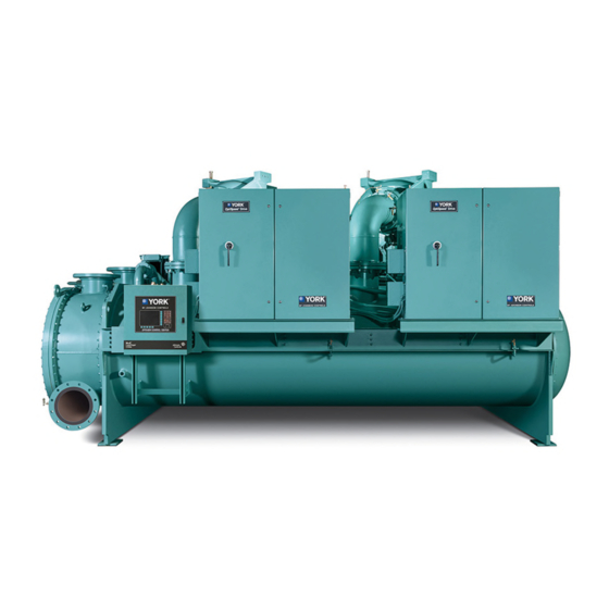
Dimensions and weights Figure 5: Chiller front view Component Description System 1 Motor System 1 Compressor Optiview Control Panel Evaporator Marine Waterboxes (Optional) Hot Gas Bypass (Optional) Unit Mounted Starters/ Drives (Optional) Centrifugal Liquid Chillers... - Page 19 Figure 6: Chiller back view Component Description System 1 Motor System 1 Compressor Terminal Box Discharge Isolation Valve Marine Waterbox Condenser Oil Sump Housing Variable Speed Oil Pump Control Panel System 2 Motor Note: No starters shown Centrifugal Liquid Chillers...
-
Page 20: Unit Dimensions
Unit dimensions See Table 1 for specific dimensions based on Evaporator-Condensor shell combinations. Figure 7: Dimensions - K compressor units ft.–in. (mm) Centrifugal Liquid Chillers... - Page 21 Table 1: YD Style D unit dimensions Dimension Evaporator-condenser shell codes dimensions, ft-in (mm) type 10' 11" 11' 3" 11' 8" 11' 8" 12' 1" 13' 10" 15' 3" 15' 2" 15' 6" 16' 11" (3,327) (3,429) (3,556) (3,556) (3,683) (4,216) (4,648) (4,623)
- Page 22 Table 3: Approximate unit weight including motor and 150 psig (1.14 MPa) compact waterboxes Shipping, lb Est. refrigerant charge, Operation weight, Shells Compressor (kg) lb (kg) lb (kg) 41,309 (18,737) 54,860 (24,884) 4060 (1841) 46,740 (21,201) 59,674 (27,068) 5040 (2286) 74,800 (33,926) 92,500 (41,953) 5635 (2555)
-
Page 23: Knocked-Down Unit Component Dimensions - Evaporator
Knocked-down unit component dimensions - evaporator Figure 8: Evaporator section dimensions Table 4: Evaporator section dimensions Dimensions ft-in (mm) Unit model compr/shells H9/Q shells 16' 0" (4877) 6' 0" (1829) 7' 6" (2286) H9/R shells 16' 0" (4877) 6' 4" (1930) 7' 9"... - Page 24 Table 5: Evaporator shell weights – 150# design, no hot gas bypass, no water boxes, 0.025 tubes Shell code Weight 11700 25740 12200 26840 12600 27720 13400 29480 14000 30800 14300 31460 14700 32340 15200 33440 15700 34540 14800 32560 15300 33660 15700...
- Page 25 Table 5: Evaporator shell weights – 150# design, no hot gas bypass, no water boxes, 0.025 tubes Shell code Weight 37600 82720 38700 85140 39900 87780 49200 108240 51300 112860 53300 117260 44400 97680 45800 100760 47300 104060 47200 103840 48800 107360 50800...
-
Page 26: Knocked-Down Unit Component Dimensions - Condenser
Knocked-down unit component dimensions - condenser Figure 10: Condenser section dimensions Table 6: Condenser section dimensions Dimensions ft-in (mm) Unit model compr/shells H9/Q shells 16' 0" (4877) 5' 0" (1524) 7' 4" (2235) H9/R shells 16' 0" (4877) 5' 3" (1600) 7' 7"... - Page 27 Table 7: Condenser shell weights – 150# design, no hot gas bypass, no water boxes, 0.025 tubes Shell code Weight 11200 24640 12000 26400 12900 28380 12900 28380 13600 29920 14200 31240 13100 28820 13900 30580 14900 32780 15500 34100 16200 35640 16700...
- Page 28 Table 7: Condenser shell weights – 150# design, no hot gas bypass, no water boxes, 0.025 tubes Shell code Weight 32900 72380 34300 75460 35100 77220 27100 59620 28100 61820 28900 63580 30300 66660 35700 78540 37600 82720 36400 80080 40200 88440 30500...
-
Page 29: Knocked-Down Unit Component Dimensions - Driveline
Knocked-down unit component dimensions - driveline Figure 11: Driveline section dimensions Table 8: Driveline section (two) Dimensions, ft-in (mm) Unit model compressor 12' 0" (3658) 6' 6" (1981) 7' 0" (2134) 10’ 9” (3277) 6’ 6” (1981) 7’ 8” (2337) 10’ 9” (3277) 6’... - Page 30 Table 9: Evaporator compact water boxes, weights, 150# design, Victaulic Shell code 1 pass (EA) 2 pass Return 3 pass (EA) 1340 1648 1373 1492 1612 3546 1877 4129 1523 3351 1780 3916 2159 4750 2444 5377 2187 4811 2445 5379 2159 4750...
- Page 31 Table 12: Condenser marine water boxes, weights, 150# design, Victaulic Shell 1 pass 3 pass Cover 2 pass Kg Return code (EA) (EA) plate 1222 2688.4 1271 2796.2 1255 2761 1798 3955.6 1391 3060.2 1491 3280.2 1373 1484 3264.8 2137 4701.4 1783 3922.6...
- Page 32 Table 14: Approximate unit motor weights, premium effeciency motors, low voltage - English (metric) 60 Hertz 50 Hertz Motor code Hp Weight, lb Weight, kg Motor code Hp Weight, lb Weight, kg 2380 1082 2469 1122 2425 1102 2491 1132 2469 1122 2535...
- Page 33 Table 15: Approximate unit motor weights, medium voltage - English (metric) Model Model Weight, lb Weight, kg Weight, lb Weight, kg 3595 1,634 4345 1,975 3690 1,677 4415 2,007 4345 1,975 4445 2,020 4415 2,007 4540 2,064 4445 2,020 4640 2,109 4540 2,064...
-
Page 34: Neoprene Isolators
Neoprene isolators The following figures apply for unit operating weights 0 lb to 116,000 lb (0 kg to 52,617 kg). Figure 12: Neoprene isolators dimensions (inches) 0 to 116,000 lbs Note: * See Figure 7. Figure 13: Neoprene isolators dimensions (mm) Note: * See Figure 7. Centrifugal Liquid Chillers... - Page 35 The following figures apply for unit operating weights 116,000 lb to 140,000 lb (52,617 kg to 63,503 kg). Figure 14: Neoprene isolators dimensions (inches) 116,000 to 140,000 lbs Note: * See Figure 7. Figure 15: Neoprene isolators dimensions (mm) Note: * See Figure 7. Centrifugal Liquid Chillers...
- Page 36 The following figures apply for unit operating weights 140,000 lb to 232,000 lb (63,503 kg to 105,233 kg). Figure 16: Neoprene isolators dimensions (inches) 140,000 to 232,000 lbs Note: * See Figure 7. Figure 17: Neoprene isolators dimensions (mm) Note: * See Figure 7. Centrifugal Liquid Chillers...
- Page 37 The following figures apply for unit operating weights 232,000 lb to 280,000 lb (105,233 kg to 127,006 kg). Figure 18: Neoprene isolators dimensions (inches) 232,000 to 280,000 lbs Note: * See Figure 7. Figure 19: Neoprene isolators dimensions (mm) Note: * See Figure 7. Centrifugal Liquid Chillers...
- Page 38 Spring isolators Figure 20: Spring isolators Centrifugal Liquid Chillers...
-
Page 39: Installation And Reassembly
Installation and reassembly Rigging unit to final location Rig the unit to its final location on the floor or mounting pad, lift the unit (or shell assembly) by means of an overhead lift and lower the unit to its mounting position. (If optional shipping skids are used, remove them before lowering the chiller to its mounting position.) Note: Units shipped dismantled should be assembled under the supervision of a Johnson Controls representative. -
Page 40: Piping Connections
Piping connections After the unit is leveled (and wedged in place for optional spring isolators) the piping connections may be made: chilled water, condenser water, and refrigerant relief. The piping must be arranged with offsets for flexibility, and adequately supported and braced independently of the unit to avoid strain on the unit and vibration transmission. - Page 41 Figure 21: Schematic of a typical piping arrangement Condenser water circuit For proper operation of the unit, condenser refrigerant pressure must be maintained above evaporator pressure. If operating conditions will fulfill this requirement, no attempt should be made to control condenser water temperature by means of automatic valves, cycling of the cooling tower fan or other means, since chillers are designed to function satisfactorily and efficiently when condenser water is allowed to seek its own temperature level at reduced loads and off-peak seasons of the year.
-
Page 42: Refrigerant Relief Piping
the chilled and condenser water circuits, operate the pumps manually and carefully check the evaporator and condenser water heads and piping for leaks. Repair leaks as necessary. Before initial operation of the unit both water circuits should be thoroughly vented of all air at the high points. -
Page 43: Unit Piping
Compressor lubricant piping and system external piping are factory installed on all units shipped assembled. On units shipped dismantled, the following piping should be completed under the supervision of the Johnson Controls representative: (1) the lubricant piping to oil sump and oil evaporator and system oil return connections using material furnished. -
Page 44: Control Wiring
Note: Remote electromechanical starters for the chiller must be furnished in accordance with the Remote Starter Specification (Form 160.79-PW4) to provide the features necessary for the starter to function properly with the YORK control system. Each chiller unit is furnished for a specific electrical power supply as stamped on the Unit Data Plate, which also details the motor connection diagrams. -
Page 45: Insulation
Figure 25: Compressor motor field connections diagram (floor mounted) Insulation CAUTION DO NOT field insulate until the unit has been leak tested under the supervision of the Johnson Controls representative. Insulation of the type specified for the job, or minimum thickness to prevent sweating of 30°F (-1°C) surfaces should be furnished (by others) and applied to the evaporator shell, end sheets,... -
Page 46: Installation Checklist And Request For Start-Up
After the unit is installed, piped and wired as described in this Instruction, but before any attempt is made to start the unit, the Johnson Controls Office should be advised so that the start-up service, included in the contract price, can be scheduled. Complete the Installation Checklist and Request for Startup Engineer (Form 160.79-CL1 and send to the Johnson Controls office. - Page 47 Note that the actuator valve uses O-rings instad of a flat gasket. If you use any oil on the O- ring, ensure that you use York K oil. See the discharge line weight in Table 19. Lift a compressor/motor assembly and remove the packing materials (see Figure 26 for rigging).
- Page 48 Table 19: Suction / discharge piping Evap code Cond code Suction line with flanges Discharge line Connect the oil drain lines between the compressors oil drain flanges and oil pump housing flanges. Be sure to install the proper gaskets and hardware, see Figure 27 The oil pump and heater wiring have been disconneted at the unit VSOP panel, see Figure 35.
- Page 49 Figure 28: Liquid line reassembly Tighten all hardware installed from the previous steps 2 through 8. Assemble the Control Center to unit. 10. Assemble the VS Oil Pump Control Panel. 11. Install high pressure cutout tubing. See Figure 29. Figure 29: High pressure cutout tubing 12.
- Page 50 Figure 30: Compressor vent piping Compressor Vent Piping H9, K1, K2 Compressor Vent Piping K3, K4, K7 LD23045 Centrifugal Liquid Chillers...
- Page 51 Figure 31: Oil supply line Oil Supply Lines LD23047 Centrifugal Liquid Chillers...
- Page 52 Figure 32: Liquid injection K3, K4 and K7 Liquid Injection K3, K4, K7 LD23046 Centrifugal Liquid Chillers...
- Page 53 Figure 33: Compressor oil return piping K3, K4, and K7 Compressors K3, K4, and K7 Compressors Compressor #2 Compressor #1 Compressor #1 and 2 K1 and K2 Compressors Condenser H.P. Gas From Compressor Connection Oil Return Connection From Evaporator Oil Return To Oil Pump Connector Housing...
- Page 54 Figure 33: Compressor oil return piping Compressor #1 Compressor #2 H9 Compressor Only K3, K4, and K7 H9, K1, and K2 Compressors Compressors LD23317 Centrifugal Liquid Chillers...
- Page 55 Figure 34: Oil cooler refrigerant piping Detail A See Detail A LD23048 Centrifugal Liquid Chillers...
- Page 56 Figure 35: Reassembly Item Description Item Description Motor Oil drain line Compressor #1 Compressor #2 Gasket Oil drain line (flexible metal braided) Isolation valve with actuator Elbow assembly O-ring Compressor support Oil pump housing VSOP panel Centrifugal Liquid Chillers...
- Page 57 VSD reassembly Install VSD bracket assembly. Lift the Variable Speed Drive and remove all packing material, for Variable Speed Drive weight see Table 16. Carefully lower the Variable Speed Drive on to the supports on the condenser. Fasten the VariableSpeed Drive to the condenser and to the motor terminal box duct. Make all necessary connections for the VSD cooling loop to be complete.
- Page 58 Figure 38: VSD bracket installed Reconnect motor power leads in the Variable Speed Drive to T1, T2, and T3 terminals and torque to 18 ft-lb to 20 ft-lb as outlined in the labels in the VSD. If provided, connect the motor winding thermistor shielded cable conductors in the Variable Speed Drive at TB4.
-
Page 59: Unit Conversion
Unit conversion The following factors can be used to convert from English to the most common SI Metric values. Table 20: SI metric conversion Measurement Multiply English unit By factor To obtain metric unit Capacity Tons Refrigerant Effect (ton) 3.516 Kilowatts (kW) Power Horsepower... - Page 60 © 2020 Johnson Controls. 5000 Renaissance Drive, New Freedom, York, PA 17349, USA. Subject to change without notice. All rights reserved...
Need help?
Do you have a question about the YORK and is the answer not in the manual?
Questions and answers