Advertisement
Quick Links
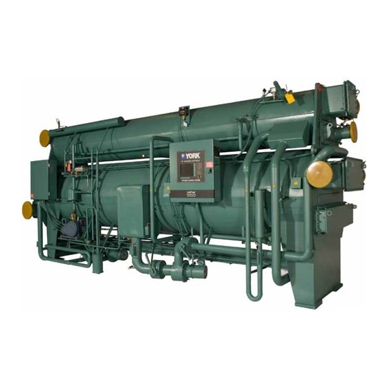
PRODUCT DRAWING
CONTRACTOR _______________________
ORDER NO. _________________________
YORK CONTRACT NO. _________________
YORK ORDER NO. ____________________
REFERENCE
DATE ________
JOB DATA:
CHILLER MODEL NO. _________________
NO. OF UNITS ________________________
Chiller design allows for ease of interfacing with Energy
Management Systems (EMS). The OptiView™ Control
Center includes unit status contacts, provisions for re‑
mote control inputs and provisions for remote setpoint
reset of leaving chilled liquid temperature and current
limit for EMS interfacing.
Five sets of unit status contacts are factory furnished
through a field wiring terminal board in the Optiview
Control Center. Each set of contacts are single pole,
normally open, rated at 5 amperes resistive at 240VAC.
Chiller status contacts are provided for unit:
• Remote Mode Ready to Start – See Fig. 3.
• Cycling Shutdown – See Fig. 4.
• Safety Shutdown – See Fig. 5.
• Run (System Operating) – See Fig. 6.
• Anticipatory/Alarm – See Fig. 7.
Four sets of inputs are available to the EMS, allowing
for remote control of unit operation. input device contact
rating shall be 5 milliamperes at 115VAC. Field wiring
terminal board (TB4) in the OptiView™ Control Center
permits connection for the following operations:
• Remote Stop Contacts – See Fig. 8.
• Remote Start Contacts – See Fig. 8.
• Remote/Local Cycling Devices – See Fig. 9.
• Multi-unit sequence – See Fig. 10.
1. The OptiView™ Control Center has a program‑
mable time clock function as a standard feature
with holiday capability. This offers one preset au‑
tomatic Start‑Stop per day on a seven day calendar
NEW RELEASE
PURCHASER ____________________________________________
JOB NAME ______________________________________________
LOCATION
ENGINEER ______________________________________________
APPROVAL
ENERGY MANAGEMENT SYSTEMS
WIRING DIAGRAM
FIELD CONTROL MODIFICATIONS
MODEL YIA CHILLERS (STYLE D)
_____________________________________________
DATE ________
CHILLER MODEL NO. _______________________
NO. OF UNITS ______________________________
basis with the ability to program a single additional
holiday start and stop time up to a week in advance.
Chilled water pump control contacts (see Note 13)
are also provided, allowing for efficient automatic
operation of the chilled water pump to reduce en‑
ergy. Two chilled water pump operating modes are
available via the CHW PUMP programming dip
switch (position 8 of SW1) on the Microboard.
With the switch in the OFF position, the chilled
water pump operates for 30 seconds prior to chiller
start, during chiller operation, coastdown, and LWT
cycling shutdowns. With the switch in the ON posi‑
tion, the chilled water pump operates as above plus
it operates during MULTI-UNIT and REMOTE/
LOCAL cycling shutdowns.
2. The Johnson Controls E-Link Gateway Card may
be interfaced with the chiller OptiView™ Control
Center to provide unified chiller plant system
control. The owners BAS System directly com‑
municates with the OptiView™ Control Center via
the E-Link Gateway Card which may be installed
in the Control Center. Temperatures, pressures,
safety alarms and cycling information known to
the OptiView™ Control Center are then available
to the owners BAS network for integrated chiller
plant control, data logging, and local and remote
operator displays. The E-Link Gateway Card also
allows the BAS network to start, stop, and reset the
chiller's leav ing chilled water and remote load set‑
points. The E-Link may be configured for BAC-net,
MS/TP, Mod-Bus RTU, N2 Metasys and Lonworks
network protocols.
Form 155.21-W2 (1209)
CONSTRUCTION
DATE ________
Advertisement

Related Manuals for Johnson Controls York YIA Series


Summary of Contents for Johnson Controls York YIA Series
- Page 1 • Cycling Shutdown – See Fig. 4. LOCAL cycling shutdowns. • Safety Shutdown – See Fig. 5. 2. The Johnson Controls E-Link Gateway Card may • Run (System Operating) – See Fig. 6. be interfaced with the chiller OptiView™ Control Center to provide unified chiller plant system •...
-
Page 2: Read Before Proceeding
All wiring must be in accordance with YORK’s published specifications and must be performed oNly by qualified Johnson Controls personnel. Johnson Controls will not be responsible for damages/problems resulting from improper connections to the controls or application of improper control signals. - Page 3 FIG. 21 – RUN CONTACTS / REMOTE RUN LIGHT AND SHUTDOWN INDICATOR PLUS EMS ....................13 FIG. 22 – AUXILIARY SAFETY SHUTDOWN INPUT ..............13 FIG. 23 – EVAPORATOR FLOW SENSORS ................14 FIG. 24 – PADDLE TYPE FLOW SENSOR ................14 FIG. 25 – GENERATOR BACKUP TRANSFER ................14 JOHNSON CONTROLS...
- Page 4 FORM 155.21-W2 (1209) LD14447 FIG. 1 – MICROBOARD (031-02430-005) 71 70 C6 C5 RV10 1 20 55 56 27 42 LD06820 FIG. 2 – I/O BOARD (031-01743-002) JOHNSON CONTROLS...
- Page 5 “CYCLING SHUTDOWN – AUTO RESTART” on the erating. The OptiView™ Control Center will display a System Status Bar and the cause of the shutdown on the System Run Message. System Details Bar of the display. Cycling Shutdown contacts function in all operating modes. JOHNSON CONTROLS...
- Page 6 Stop Contacts open, and the Remote Mode Ready to as a standard feature; an additional Start Contacts closed (Fig. 3), the unit will start via program timer is not required for this a closure of the Re mote Start Contacts. A subsequent function. JOHNSON CONTROLS...
- Page 7 “System Run” and continuously thereafter. The OptiView Control Panel allows the use of either the The OptiView Control Center will display the following Thermal-type or Paddle-type flow sensor. message: “SAFETY SHUTDOWN” and “CONDENS‑ ER WATER FLOW SWITCH OPEN”. JOHNSON CONTROLS...
- Page 8 1/2" NPT brass well (maximum liquid DWP 300 PSIG). The thermostat is drawn to indicate its operation closes on rise. A 1/2" pipe coupling in the return chilled water line from the building must be furnished (by others) for RWT control well. JOHNSON CONTROLS...
- Page 9 For individual unit is avoided. When one unit is cut-out by the sequence chilled water pump piping, refer to Fig. 14. control (Fig. 12) the temperature of the supply chilled water does not change. JOHNSON CONTROLS...
- Page 10 • The appropriate signal source mode must be se‑ control center. lected. It is recommended that a qualified YORK/ Johnson Controls service technician accomplish this Any locally programmed settings will in the local/service mode on the OptiView control take presentence over the remote set‑...
- Page 11 “Remote Reset Range” must be set‑ up locally on the OptiView panel by a qualified YORK/ Johnson Controls service technician. This parameter is the maximum allowable offset of the leaving chilled liquid setpoint when operating in the Remote mode.
- Page 12 It is recommended that a qualified YORK/ be employed to energize a local or remote safety alarm Johnson Controls service technician accomplish this (by others). When the normally open Safety Shutdown in the local/service mode on the OptiView control Contacts close, the alarm will indicate shutdown of the center.
- Page 13 DOWN". The unit will not restart until the contacts open and the keypad "unit" switch is moved to the “STOP/ RESET” position and then to the “START” position. LD06836 FIG. 21 – RUN CONTACTS / REMOTE RUN LIGHT AND SHUTDOWN INDICATOR PLUS EMS JOHNSON CONTROLS...
- Page 14 Refer to 155.21-O1 for additional details on the limited dilution cycle. When no flow of liquid is sensed, the relay output is turned off, this results in less than 1VDC to the micro‑ Refer to 155.21-EG1 for minimum power requirements board input. for standby power supply. JOHNSON CONTROLS...
- Page 15 Two flow Manual restart to Auto restart after a power failure, For switches, a flow switch and a relay or separate contacts details consult a qualified YORK/Johnson Controls on the same flow switch. service technician.
- Page 16 P.O. Box 1592, York, Pennsylvania USA 17405-1592 Tele. 800-861-1001 Subject to change without notice. Printed in USA Copyright © by Johnson Controls Inc. 2009 www.york.com ALL RIGHTS RESERVED Form 155.21-W2 (1209) NEW RELEASE...
Need help?
Do you have a question about the York YIA Series and is the answer not in the manual?
Questions and answers