
Subscribe to Our Youtube Channel
Related Manuals for Johnson Controls YORK YVAM


Summary of Contents for Johnson Controls YORK YVAM
- Page 1 YVAM Air-Cooled Centrifugal Liquid Chiller Field Installation Procedure for YVAM Units with 20 Fans, HFC-134A, 60 Hz 035-28539-000 Installation Guide Form Number: 160.88-N1 (122) Issue Date: 2022-01-21 New Release...
- Page 2 YVAM Air-Cooled Centrifugal Liquid Chiller...
-
Page 3: Table Of Contents
Contents General safety guidelines..........................5 C o n t e n t s Safety symbols............................5 Changeability of this document......................6 Associated literature..........................6 Nomenclature............................7 Overview................................9 Chiller components..........................9 Receiving................................. 11 Inspection............................. 11 Delivery and storage........................... 11 Chiller data plate..........................12 Rigging................................13 Scope..............................13 Lifting weights............................14 Moving the chiller.......................... - Page 4 Waterbox fill and vent..........................27 Wiring connections..........................27 Unit power wiring............................27 Unit control wiring............................. 27 Apply insulation........................... 27 Unit heater operation verification..................... 28 Reassembly..............................29 Refrigerant tubing reassembly......................30 Assembly of straight thread O-ring port fittings..................30 Assembly of O-ring face seal fittings....................... 32 Dimensions, nozzle arrangements, and weights..................
-
Page 5: General Safety Guidelines
General safety guidelines This equipment is a relatively complicated apparatus. During rigging, installation, operation, maintenance, or service, individuals may be exposed to certain components or conditions including, but not limited to: heavy objects, refrigerants, materials under pressure, rotating components, and both high and low voltage. -
Page 6: Changeability Of This Document
All wiring must be in accordance with Johnson Controls’ published specifications and must be performed only by a qualified electrician. Johnson Controls will NOT be responsible for damage/problems resulting from improper connections to the controls or application of improper control signals. -
Page 7: Nomenclature
Nomenclature Figure 1: System nomenclature Figure 2: Compressor nomenclature Figure 3: Vessel nomenclature YVAM Air-Cooled Centrifugal Liquid Chiller... - Page 8 Figure 4: Variable speed drive nomenclature YVAM Air-Cooled Centrifugal Liquid Chiller...
-
Page 9: Overview
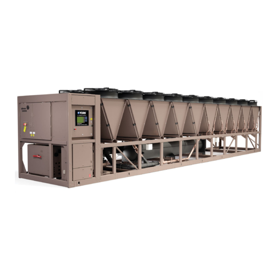
Overview This manual provides instructions for rigging and installing a Johnson Controls YVAM Liquid Chilling Unit. Chillers are shipped as a single factory-assembled, piped, and wired package. The units require a minimum of field labor to make chilled water connections and electrical power connections. - Page 10 Figure 6: Compressor side view Callout Component Callout Component Evaporator Motor cooling filter drier Expansion valve Cooling piping for variable speed drive Eaton surge suppressor Direct drive motor and MBC ® Compressor Figure 7: Variable speed drive end view Callout Component Callout Component...
-
Page 11: Receiving
If any damage is evident, it must be noted on the carrier’s freight bill and a claim entered in accordance with the instructions given on the advice note. Note: Johnson controls is not responsible for any damage in shipment or at job site or loss of parts. Refer to Shipping Damage Claims Form, Form 50.15-NM. -
Page 12: Chiller Data Plate
• When units are received, notify the nearest Johnson Controls office in ample time for a Johnson Controls representative to supervise rigging the unit to its storage or operating locations. • Do not make final power supply connections to the single point power panel or any other power connections without Johnson Controls supervision. -
Page 13: Rigging
Rigging Figure 9: Rigging warning WARNING Rigging and lifting should only be done by a professional rigger in accordance with a written rigging and lifting plan. The most appropriate rigging and lifting method depends on job specific factors, such as the rigging equipment available and site needs. A professional rigger must determine the rigging and lifting method to be used. -
Page 14: Lifting Weights
Lifting weights Note that weight can vary depending on unit configuration at the time of lifting. See Figure 11 for lifting location information. All published weights in this manual are approximate values at the time of publication. Refer to the unit nameplate or submittal documents for unit shipping weight. Moving the chiller Before moving the unit, ensure that the installation site is suitable for installing the unit and can easily support the weight of the unit and all associated services. -
Page 15: Chiller Dimensions And Rigging Locations
• Use spreader bars to avoid lifting chains hitting the chiller. Various methods of spreader bar arrangements may be used, keeping in mind the intent is to keep the unit stable and to prevent the chains from hitting the chiller and causing damage. •... -
Page 16: Installation
Foundation requirements Mount units on a flat and level foundation, ground or roof, that can support the entire operating weight of the equipment. Contact your nearest Johnson Controls Sales Office for shipping and operating weights. Ground locations For ground level locations, the unit must be installed on a suitable flat and level concrete base that extends to fully support the two side channels of the unit base frame. -
Page 17: Other Considerations
The results of the restricted airflow or hot air recirculation can diminish performance as outlined in Form 150.12-AD2, Air-Cooled Chiller Derating Due to Airflow Restrictions. Johnson Controls’ unit controls optimize the operation without nuisance high pressure safety cutouts. However, the system designer must consider the potential for performance degradation. -
Page 18: Rig Chiller To Final Location
• Provide adequate space for tubes to be removed from evaporator. For clearances, contact your nearest Johnson Controls Sales Office. Figure 12: Unit clearance dimensions, ft (m) Rig chiller to final location... -
Page 19: Leveling The Chiller
Leveling the chiller Make sure that chiller base rail remains straight along the long axis of the chiller during the leveling process. This can be accomplished with the use of a string along the base rail. Any bowing of the chiller frame can lead to refrigerant line failures or other component fatigue issues over time. -
Page 20: Isolators
This method is not recommended as an option for YVAM chillers. Vibration isolation is an important option that must be accounted for at chiller installation. If isolators are not ordered, they must be selected based on the loading at the specific chiller locations. Contact Johnson Controls representative for assistance if isolators have not been provided. - Page 21 Figure 14: Spring isolator detail Callout Description Callout Description Equipment base Isolator base Base slotted holes Spring adjusting bolt Non-skid elastomeric pad Lower housing Upper housing Positioning pin Figure 15: One inch deflection spring isolators Table 3: Spring isolator dimension data, in. Mount type Type A 7 3/4...
-
Page 22: Installation Of Optional Elastomeric Isolators
The following table shows the rated capacity for units with all load points less than 1785 lb (810 kg). Table 4: Type A model detail Type A model P/N Color code Rated capacity, lb Rated capacity, kg YORK P/N 029-25334-002 (433668) Black Up to 434 Up to 197 029-25334-002... - Page 23 To complete the installation, reinstall the top bolt and washer and tighten. Figure 16: Elastomeric isolator details Callout Description Callout Description Isolator base Base slotted holes Isolator threaded hole Cross section points Top washer Top bolt Note: Isolators generally appear square or rectangular in appearance. Figure 17: Elastomeric isolator cross reference, Type A isolators Table 6: Elastomeric isolator dimension data, in.
-
Page 24: Make Piping Connections
Compressor refrigerant piping and system external piping are factory installed on all units. On units where the chiller refrigerant piping must be removed for any reason, the piping must only be completed under the direct supervision of the Johnson Controls representative. Evaporator freeze damage CAUTION Power must remain on the chiller whenever the ambient temperature drops below 32°F (0°C) with... - Page 25 adequately supported and braced independently of the chiller to avoid pipe strain on the chiller and for isolation of vibration transmission. • Hangers must allow for alignment of pipe. Isolators (by others) in the piping are a preferred option, and may be required by specifications in order to effectively use the vibration isolation characteristics of the vibration isolation mounts of the unit •...
-
Page 26: Check For Piping Alignment
CAUTION Any debris left in the water piping between the strainer and evaporator could cause serious damage to the tubes in the evaporator and must be avoided. Be sure the piping is clean before connecting it to the evaporator. Keep evaporator nozzles and chilled liquid piping capped before installation to ensure construction debris is not allowed to enter. -
Page 27: Waterbox Drain And Vent Valves
Note: No deviations in unit wiring from that shown on drawings furnished will be made without prior approval of the Johnson Controls representative. Apply insulation All evaporator parts are factory insulated on the shell surfaces, end sheets, liquid feed line to flow chamber, compressor suction connection, and evaporator liquid heads and water connection nozzles. -
Page 28: Unit Heater Operation Verification
Unit heater operation verification The YVAM chiller uses various heaters to protect all of the devices that are susceptible to low ambient temperature limits. As part of the commissioning process of the chiller, it is important to verify operation of these heaters to ensure reliability of these various components. Verification of heater operation should be logged using the current values for each heater in Form 160.88- CL2 during chiller commissioning. -
Page 29: Reassembly
For occasions where field disassembly or reassembly may need to be conducted for any reason, the following sections are intended to provide technical details for a qualified Johnson Controls Service representative to safely complete these tasks. Table 8: Assembly torque metric for metric tube fittings... -
Page 30: Refrigerant Tubing Reassembly
Table 10: Chiller hardware torque values Location Description Quantity Torque value ft·lb N•m Suction line flange at M24 X 3 / 90 mm long 021-33185-090 731065 compressor Discharge line flange at M20 X 2.5 / 70 mm 021-33184-070 731064 compressor long Liquid line shutoff valve inlet M16 X 2 / 60 mm long... - Page 31 Figure 19: Back off locknut Screw the fitting into the port until the back-up washer contacts the face of the port. Light wrenching may be necessary. Figure 20: Screw fitting into port To align the tube end of fitting to accept incoming tube or hose assembly, unscrew by required amount, but not more than one full turn.
-
Page 32: Assembly Of O-Ring Face Seal Fittings
Straight non-adjustable end assembly Inspect to ensure that both matching parts are free of burrs, nicks, scratches, or any foreign particles. If the O-ring is not pre-installed, install the O-ring on the port end of fitting. Use care not to nick the O-ring. -
Page 33: Dimensions, Nozzle Arrangements, And Weights
Dimensions, nozzle arrangements, and weights The following figure shows the detail of the evaporator 150 psi compact two-pass waterboxes. Figure 23: Two-pass waterbox detail, mm (in.) YVAM Air-Cooled Centrifugal Liquid Chiller... - Page 34 The following figure shows the detail of the evaporator 150 psi compact three-pass waterboxes. Figure 24: Three-pass waterbox detail, mm (in.) Table 11: Two-pass and three-pass compact 150 psi nozzle arrangements Two-pass nozzle arrangements Three-pass nozzle arrangements Lower rear side Upper rear side Lower rear side Upper front side...
- Page 35 Table 13: Refrigerant and water weights Evaporator Condenser Refrigerant weight, lb (kg) Water weight, lb (kg) EB2514 2 5mm 4G microchannel 700 (318) 1680 (762) Table 14: Waterbox weights Approximate evaporator and waterbox weights Evaporator Compact waterbox weights, lb (kg) Code Weight, lb (kg) One-pass...
-
Page 36: Unit Conversion
To convert a temperature range (i.e., a range of 10°F) from Fahrenheit to Celsius, multiply by 5/9 or 0.5556. Example: 10.0°F range x 0.5556 = 5.6 °C range © 2022 Johnson Controls. 5000 Renaissance Drive, New Freedom, York, PA 17349, USA. Subject to change without notice. All rights reserved.
Need help?
Do you have a question about the YORK YVAM and is the answer not in the manual?
Questions and answers