Table of Contents
Advertisement
Quick Links
Advertisement
Table of Contents

Subscribe to Our Youtube Channel
Related Manuals for Johnson Controls York OptiView YK G Series


Summary of Contents for Johnson Controls York OptiView YK G Series
- Page 1 Model YK Style G R-134a or R-513A with OptiView™ Control Center for Electromechanical Starter, Solid State Starter, and Variable Speed Drive Operations and Maintenance Form number: 160.75-O1 (621) Issue Date: 2021-06-05 Supersedes: 160.75-O1 (820)
- Page 2 Model YK Style G R-134a or R-513A...
-
Page 3: Table Of Contents
Contents General safety guidelines..........................5 C o n t e n t s Safety symbols............................. 5 Changeability of this document......................6 Associated literature........................... 6 Conditioned based maintenance...................... 7 Nomenclature............................7 Description of system and fundamentals of operation................8 System operation description......................8 Capacity control........................... - Page 4 Oil charging procedure........................27 Troubleshooting............................28 Maintenance..............................31 Renewal parts............................ 31 Checking system for leaks........................ 31 Conducting an R-22 pressure test....................31 Evacuation and dehydration of unit....................32 Vacuum testing..........................33 Vacuum dehydration......................... 33 Operation............................33 Refrigerant charging......................... 34 Checking the refrigerant charge during unit shutdown.............. 35 Handling refrigerant for dismantling and repairs................
-
Page 5: General Safety Guidelines
General safety guidelines This equipment is a relatively complicated apparatus. During rigging, installation, operation, maintenance, or service, individuals may be exposed to certain components or conditions including, but not limited to: heavy objects, refrigerants, materials under pressure, rotating components, and both high and low voltage. -
Page 6: Changeability Of This Document
All wiring must be in accordance with Johnson Controls’ published specifications and must be performed only by a qualified electrician. Johnson Controls will not be responsible for damage/problems resulting from improper connections to the controls or application of improper control signals. -
Page 7: Conditioned Based Maintenance
Traditional chiller maintenance is based upon assumed and generalized conditions. In lieu of the traditional maintenance program, a Johnson Controls YORK conditioned based maintenance (CBM) program can be substituted. This CBM service plan is built around the specific needs for the chiller, operating conditions, and annualized impact realized by the chiller. -
Page 8: Description Of System And Fundamentals Of Operation
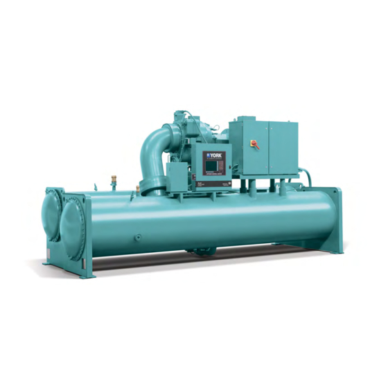
Description of system and fundamentals of operation System operation description The YORK Model YK Chiller is commonly applied to large air conditioning systems, but can be used on other applications. The chiller consists of an open motor mounted to a compressor with integral speed increasing gears, condenser, evaporator and variable flow control. -
Page 9: Capacity Control
Figure 2: Compressor pre-rotation vanes The refrigerant vapor, which is produced by the boiling action in the evaporator, flows to the compressor where the rotating impeller increases its pressure and temperature and discharges it into the condenser. Water flowing through the condenser tubes absorbs heat from the refrigerant vapor, causing it to condense. - Page 10 Figure 3: Refrigerant flow-through chiller (falling film evaporator) Model YK Style G R-134a or R-513A...
- Page 11 Figure 4: Refrigerant flow-through chiller (flooded evaporator) Model YK Style G R-134a or R-513A...
-
Page 12: System Operating Procedures
System operating procedures Oil heaters If the oil heater is de-energized during a shutdown period, it must be energized for 12 hours prior to starting the compressor, or remove all the oil and recharge the compressor with new oil. See charging procedure. -
Page 13: Start-Up Procedure
CAUTION Comply with EPA and local regulations when removing or disposing of refrigeration system oil. Start-up procedure Pre-starting Before starting the chiller, observe the OptiView™ Control Center – Operation and Maintenance (Form 160.54-O1). Ensure that the display reads SYSTEM READY TO START. CAUTION Vent any air from the chiller waterboxes prior to starting the water pumps. - Page 14 Chiller starting sequence and shutdown sequence Figure 6: Chiller starting sequence and shutdown sequence (EM starter and solid state starter) Note: ** Not for all shutdowns. Refer to Display Messages in the manual OptiView™ Control Center – Operation and Maintenance (Form 160.54-O1). Figure 7: Chiller starting sequence and shutdown sequence (variable speed drive) Note: ** Not for all shutdowns.
-
Page 15: Chiller Operation
For display messages and information pertaining to the operation, refer to OptiView™ Control Center – Operation and Maintenance (Form 160.54-O1). Note: Any malfunctions which occur during STOP/RESET are also displayed. Chiller operation The unit capacity varies to maintain the leaving Chilled Liquid Temperature setpoint by the pre-rotation vanes, which are modulated by an actuator under the control of the microprocessor board. -
Page 16: Operating Inspections
An optional status printer is available for this purpose. Alternatively, Figure 8 shows a log sheet used by Johnson Controls Personnel for recording test data on chiller systems. It is available from the factory in pads of 50 sheets each under Form 160.44-F6 and can be obtained through the nearest Johnson Controls office. -
Page 17: Need For Maintenance Or Service
Check the compressor discharge temperature on the System Screen. During normal operation discharge temperature should not exceed 220°F (104°C). Check the compressor motor current on the System Screen. Check for any signs of dirty or fouled condenser tubes. The temperature difference between water leaving condenser and saturated condensing temperature should not exceed the difference recorded for a new unit by more than 4°F (2.2°C). -
Page 18: Stopping The System
Johnson Controls District Office. Failure to report persistant trouble could damage the unit and increase the cost of repairs. Stopping the system About this task: The OptiView™ control center can be programmed to start and stop automatically (maximum, once each day) whenever desired. -
Page 19: System Components Description
System components description General The YORK Model YK centrifugal liquid chiller is completely factory-packaged including the evaporator, condenser, compressor, motor, lubrication system, OptiView™ control center, and all interconnecting unit piping and wiring. Compressor The compressor is a single-stage centrifugal type powered by an open-drive electric motor. The rotor assembly consists of a heat-treated alloy steel drive shaft and impeller shaft with a cast aluminum, fully shrouded impeller. -
Page 20: Oil Pump
The submerged oil pump takes suction from the surrounding oil and discharges it to the oil cooler where heat is rejected. The oil flows from the oil cooler to the oil filter. The oil leaves the filter and flows to the emergency oil reservoir where it is distributed to the compressor bearings. The oil lubricates the compressor rotating components and is returned to the oil sump. - Page 21 Figure 10: System components rear view Model YK Style G R-134a or R-513A...
- Page 22 Figure 11: Schematic drawing – (YK) compressor lubrication system Model YK Style G R-134a or R-513A...
-
Page 23: Oil Heater
Oil heater During long idle periods, the oil in the compressor oil reservoir tends to absorb as much refrigerant as it can hold, depending upon the temperature of the oil and the pressure in the reservoir. As the oil temperature is lowered, the amount of refrigerant absorbed increases. If the quantity of refrigerant in the oil becomes excessive, violent oil foaming results as the pressure within the system is lowered on starting. -
Page 24: Refrigerant Flow Control
chiller efficiency. An integral sub- cooler is located at the bottom of the condenser shell providing highly effective liquid refrigerant subcooling to provide the highest cycle efficiency. The condenser contains dual refrigerant relief valves set at 235 psig (16.2 barg). The removable waterboxes are fabricated of steel. -
Page 25: Optiview™ Control Center
OptiView™ control center The OptiView™ control center is factory-mounted, wired and tested. The electronic panel automatically controls the operation of the unit in meeting system cooling requirements while minimizing energy usage. For detailed information on the control center, see System operating procedures. -
Page 26: Operational Maintenance
Operational maintenance Oil return system The oil return system continuously maintains the correct oil level in the compressor oil sump. See Figure 12. High pressure condenser gas flows continuously through the eductor inducing the low pressure, oil rich liquid to flow from the evaporator, through the dehydrator to the compressor sump. Figure 12: Oil return system Changing the dehydrator To change the dehydrator, use the following procedure:... -
Page 27: Oil Charging Procedure
New YORK Refrigeration oil must be used in the centrifugal compressor. Since oil absorbs moisture when exposed to the atmosphere, it should be kept tightly capped until used. Oil charging procedure About this task: During operation, the compressor oil level must be maintained in the OPERATING RANGE identified on the vertical oil level indicator. -
Page 28: Troubleshooting
Troubleshooting Table 1: Operation analysis chart Results Possible cause Remedy 1. Symptom: Abnormally high discharge pressure Temperature difference between condensing temperature Air in condenser. and water off condenser higher than normal. Clean condenser Condenser tubes tubes. dirty or scaled. Check water conditioning. - Page 29 Table 1: Operation analysis chart Results Possible cause Remedy Check the pre-rotation Pre-rotation vanes vane motor fail to open. positioning circuit. High chilled water temperature. Be sure the vanes are wide open (without System overload. overloading the motor) until the load decreases.
- Page 30 Table 1: Operation analysis chart Results Possible cause Remedy Filter-drier in oil Replace old filter- return system drier with new. dirty. Remove jet, Oil refrigerant return not functioning. inspect for dirt. Jet or orifice of oil Remove dirt return jet clogged. using solvent and replace.
-
Page 31: Maintenance
Maintenance Renewal parts For any required Renewal Parts, refer to the Renewal Parts – Unit (Form 160.75-RP1). Checking system for leaks Leak testing during operation The refrigerant side of the system is carefully pressure tested and evacuated at the factory. After the system has been charged, the system should be carefully leak tested with a R-134a compatible leak detector to be sure all joints are tight. -
Page 32: Evacuation And Dehydration Of Unit
Evacuation and dehydration of unit Figure 14: Evacuation of chiller Table 2: System pressures Absolute Gauge Inches of Boiling mercury (Hg) temperatures Millimeters of below one psia Microns of water °F mercury (Hg) standars atmosphere 14.696 760.00 760,000 10.2400 in. 9.629 500.00 500,000... -
Page 33: Vacuum Testing
Vacuum testing About this task: After the pressure test has been completed, the vacuum test should be conducted as follows: Connect a high capacity vacuum pump, with indicator, to the system charging valve as shown in Figure 14 and start the pump. See Vacuum dehydration. -
Page 34: Refrigerant Charging
If the system has been pressure tested and found to be tight prior to evacuation, then the saturation temperature recordings follow a curve similar to the typical saturation curve shown as Figure 15. The temperature of the water in the test tube drops as the pressure decreases, until the boiling point is reached, at which point the temperature levels off and remains at this level until all of the water in the shell is vaporized. -
Page 35: Checking The Refrigerant Charge During Unit Shutdown
be purged each time a full container of refrigerant is connected, and changing containers should be done as quickly as possible to minimize the loss of refrigerant. Refrigerant is furnished in cylinders containing either 30, 50, 125, 1,025 or 1750 lbs. (13.6, 22.6, 56.6, 464 or 794 kg) of refrigerant. -
Page 36: Megging The Motor - Mechanical Starter
Megging the motor - mechanical starter While the main disconnect switch and compressor motor starter are open, meg the motor as follows: Using a megohm meter (megger), meg between phases and each phase to ground. See Figure 16. Interpret these readings using the graph shown in Figure 18. If readings fall below the shaded area, remove the external leads from the motor and repeat the test. - Page 37 Figure 18: Motor starter temperature and insulation resistances Condensers and evaporators Maintenance of the condenser and evaporator shells is important to provide trouble free operation of the chiller. The water side of the tubes in the shell must be kept clean and free from scale. Correct maintenance such as tube cleaning, and testing for leaks, is covered in this section.
- Page 38 Chemical water treatment Since the mineral content of the water circulated through evaporators and condensers varies with almost every source of supply, it is possible that the water being used may corrode the tubes or deposit heat resistant scale in them. Reliable water treatment companies are available in most larger cities to supply a water treating process which will greatly reduce the corrosive and scale forming properties of almost any type of water.
- Page 39 Acid cleaning of tubes If the tubes are fouled with a hard scale deposit, they may require acid cleaning. It is important that before acid cleaning, the tubes be cleaned by the brushing process first. If the relatively loose foreign material is removed before the acid cleaning, the acid solution has less material to dissolve and flush from the tubes, resulting in a more satisfactory cleaning job and a probable saving of time.
-
Page 40: Compressor
However, if aluminum particles continue to accumulate and the same conditions continue to stop the unit operation after a new filter is installed, notify the nearest Johnson Controls office to request the presence of a Johnson Controls Service Technician. -
Page 41: Preventive Maintenance
Important: If a unit failure occurs due to incorrect maintenance during the warranty period; Johnson Controls will not be liable for costs incurred to return the system to satisfactory operation. In any operating system it is most important to provide a planned maintenance and inspection of its functioning parts to keep it operating at its peak efficiency. -
Page 42: Leak Testing
The following greases can be used for standard applications at an operating ambient temperature from -30ºC to 50ºC: • Chevron SRI grease (Chevron Corporation) ® • UNIREX N 2 grease (Exxon Mobil Corporation) ® • POLYREX grease (Exxon Mobil Corporation) ®... -
Page 43: Oil Return System
Electrical controls Inspect all electrical controls for obvious malfunctions. Do not change the factory settings of controls (operation and safety). If the settings are changed without Johnson Controls approval, the warranty will be jeopardized. Model YK Style G R-134a or R-513A... - Page 44 To convert a temperature range (for example, a range of 10°F) from Fahrenheit to Celsius, multiply by 5/9 or 0.5556. Example: 10.0°F range x 0.5556 = 5.6°C range © 2021 Johnson Controls. 5000 Renaissance Drive, New Freedom, York, PA 17349, USA. Subject to change without notice. All rights reserved.
Need help?
Do you have a question about the York OptiView YK G Series and is the answer not in the manual?
Questions and answers