Ropex RESISTRON RES-440 Operating Instructions Manual
Hide thumbs
Also See for RESISTRON RES-440:
- Operating instructions manual (54 pages) ,
- Replacement instructions manual (7 pages)
Table of Contents
Advertisement
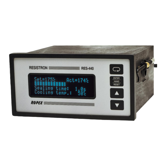
RESISTRON
RES-440
Operating
Instructions
Important features
•
Microprocessor technology
•
LC display (green), 4 lines, 20 characters, (multilingual)
Alternatively:
VF display (blue), 4 lines, 20 characters, (multilingual)
•
Automatic zero calibration (AUTOCAL)
•
Automatic optimization (AUTOTUNE)
•
Automatic configuration of the secondary voltage and current ranges
(AUTORANGE, as of software revision 100)
•
Automatic phase angle compensation (AUTOCOMP, as of software revision 100)
•
Automatic frequency adjustment
•
Large current and voltage range
•
Booster connection as standard
•
Heatsealing band alloy and temperature range selectable
•
Time control, heatsealing time and cooling time settable
•
Preheating
•
Configurable relay output, e.g. "end of cycle"
•
Time or temperature-controlled cooling phase
•
Signal output for "Temperature OK"
•
0...10VDC analog output for ACTUAL temperature
•
Alarm function with fault diagnosis
Identical design to and compatible with RES-222, -230, -241, -242
ROPEX Industrie-Elektronik GmbH
Adolf-Heim-Str. 4
74321 Bietigheim-Bissingen (Germany)
Tel.: +49 (0)7142-7776-0
Fax: +49 (0)7142-7776-211
E-Mail:
info@ropex.de
Internet:
https://ropex.de
Data subject to change
Advertisement
Table of Contents

Related Manuals for Ropex RESISTRON RES-440


Summary of Contents for Ropex RESISTRON RES-440
- Page 1 Signal output for "Temperature OK" • 0…10VDC analog output for ACTUAL temperature • Alarm function with fault diagnosis Identical design to and compatible with RES-222, -230, -241, -242 ROPEX Industrie-Elektronik GmbH Tel.: +49 (0)7142-7776-0 E-Mail: info@ropex.de Adolf-Heim-Str. 4 Fax: +49 (0)7142-7776-211 Internet: https://ropex.de...
-
Page 2: Table Of Contents
Contents General information ....4 Controller functions ....34 Copyright . - Page 3 Maintenance ......85 How to order ..... . . 86 Index .
-
Page 4: General Information
The temperature coefficient must be taken from the ROPEX application report and must be set accordingly. The use of incorrect alloys with a too low temperature coefficient and incorrect coding of the ®... -
Page 5: Impulse Transformer
The use of an original ROPEX line filter is mandatory in order to comply with the directives mentioned in section "DECLARATION OF CONFORMITY" on page 7. This device must be installed and connected according to the instructions contained in section "Power supply"... -
Page 6: Disposal
General information Disposal This device is subject to Directive 2012/19/EU concerning the reduction of the increasing amount of waste electrical and electronic equipment and the disposal of such waste in an environmentally sound way. To guarantee proper disposal and / or the recover of reusable material, please take the device to a designated municipal collection point and observe local regulations. - Page 7 We also wish to point out that the transformer which is used must be designed in accordance with VDE 0551/EN 61558 or UL 5058 for safety reasons. July 12, 2020 J. Kühner (CEO) ROPEX Industrie-Elektronik GmbH Adolf-Heim-Str. 4 74321 Bietigheim-Bissingen (Germany) Version 1...
-
Page 8: Application
Application Application ® This RESISTRON temperature controller is an integral part of the "series 400", the outstanding feature of which ® is its microprocessor technology. All RESISTRON temperature controllers are used to control the temperature of heating elements (heatsealing bands, beaded bands, cutting wires, heatsealing blades, solder elements etc.), as required in a variety of heatsealing processes. -
Page 9: Description Of The Controller
Description of the controller the system components, in other words the heatsealing band, the impulse transformer, the wiring, the timing sig- nals and the controller itself, are compatible with one another. We will be pleased to contribute our many years of experience your towards optimizing heatsealing system. -
Page 10: Accessories And Modifications
Optimized for the RESISTRON temperature controller. Impulse transformer ITR-x Designed according to EN 61558 with a one-section bobbin. Optimized for impulse operation with RESISTRON temperature controllers. Specified according to the heatsealing application ( ROPEX Application Report). Page 10 RES-440 Version 1... -
Page 11: Modifications (Mods)
Accessories and modifications Communication interface CI-USB-1 Interface for connecting a RESISTRON temperature controller with diagnostic inter- face (DIAG) to the PC (USB port). Associated PC visualization software for dis- playing setting and configuration data, and for recording SET and ACTUAL temper- atures in real time. - Page 12 Accessories and modifications MOD 01 Amplifier for low secondary voltages (U = 0.25…16VAC). This modification is necessary, for example, for very short or low-resistance heatsealing bands. MOD 33 (Software revision 010 or higher) Important heatsealing process data can be output and logged via a serial RS232 interface ( MOD 33" documen- tation).
-
Page 13: Technical Data
Technical data Technical data Type of construction Housing for front panel mounting Dimensions (W x H): 144 x 72mm; depth: 161mm (incl. terminals) Line voltage All controller manufactured as of March 2006 (as of software revision 100): 115VAC version: 110VAC -15%…120VAC +10% (equivalent to 94…132VAC) 230VAC version: 220VAC -15%…240VAC +10% (equivalent to 187…264VAC) 400VAC version: 380VAC -15%…415VAC +10% (equivalent to 323…456VAC) All controllers manufactured as of January 2004 up to February 2006... - Page 14 Technical data Digital logic levels LOW (0V): 0…2VDC Terminals 3, 4, 22 HIGH (24VDC): 12…30VDC (max. current input 6mA) Electrically isolated, reverse polarity-protected START with contact Switching threshold: 3.5VDC, U = 5VDC, I = 5mA Terminals 2+7 Switching output = 30VDC, I = 50mA for „"Output 1"/ <...
-
Page 15: Dimensions/Front Panel Cutout
Dimensions/front panel cutout Dimensions/front panel cutout panel cutout outline dimensions front frame ±0.2 ±0.2 x 68 rubber seal mounting clamp terminal wires terminal blocks terminal blocks front frame front panel terminal wires DIP-switch to select U , I Version 1 RES-440 Page 15... -
Page 16: Installation
4. Wire the system in accordance with the instructions in section 8.3 "Power supply" on page 18, section 8.6 "Wiring diagram (standard)" on page 21 and the ROPEX Application Report. The information provided in section 8.2 "Installation steps" on page 17 must be heeded additionally. -
Page 17: Installation Steps
Installation Installation steps Use heatseal bands with suitable temperature coefficient Heatseal element push-on with coppered ends connectors Heatsealing band R= f (T) No additional Connect U measuring resistance wires directly to in secondary heatsealing band ends Note circuit number Sufficient wire of turns Twisted cross-section... -
Page 18: Power Supply
Connect core to ground. Use transformers with a one section bobbin. The power, duty cycle and voltage values must be deter- mined individually according to the application ( ROPEX SEC. Application Report and "Accessories" leaflet for impulse transformers). -
Page 19: Line Filter
ROPEX line filters are specially optimized for use in RESISTRON control loops. Providing that they are installed and wired correctly, they guarantee compliance with the EMC limit values. You can find the exact specification of the line filter in the ROPEX Application Report calculated for your particular heatsealing application. - Page 20 Installation 8.5.1 PEX-W4 terminal wires terminal block Snap-on for DIN-rail 35 x 7.5 mm or 35 x 15 mm (DIN EN 50022) 8.5.2 PEX-W5 Mounting on DIN-rail 35 x 7.5 mm or 35 x 15 mm (DIN EN 50022). Page 20 RES-440 Version 1...
-
Page 21: Wiring Diagram (Standard)
Installation Wiring diagram (standard) Line filter LF-xx480 RES-440 LINE (also with MOD 01) RELAY K1 100VDC/1.5A 240VAC/1.5A 2x 47nF/560R ALARM OUTPUT max. 30V/0.2A Contact closed or prim. opened by ALARM (see configuration) Impulse transformer sec. PREHEAT Heat- with 24VDC signal sealing band twisted... -
Page 22: Wiring Diagram With Booster Connection
Installation Wiring diagram with booster connection Line filter LF-xx480 RES-440 LINE (also with MOD 01) Booster RELAY K1 100VDC/1.5A 240VAC/1.5A 2x 47nF/560R ALARM OUTPUT max. 30V/0.2A Contact closed or prim. opened by ALARM (see configuration) Impulse transformer sec. PREHEAT Heat- with 24VDC signal sealing band... -
Page 23: Startup And Operation
(on rear of controller) Nameplate Clips Display Rear view of the controller As of software revision 100: Printed wiring diagram ROPEX 19 20 21 22 23 24 25 26 16 17 18 RES-440 19 20 21 22 23 24 25 26 SEC. PRIM. -
Page 24: Controller Configuration
Set the DIP switches for matching the secondary voltage U and the secondary current I to the correct position for your application. You can find the exact configuration of the DIP switches in the ROPEX Application Report calculated for your particular application. Page 24 RES-440... - Page 25 120...400A If the secondary current I is less than 30A, the secondary high-current wire must be laid twice (or several times) through the PEX-W2 or PEX-W3 current transformer ( ROPEX Application Report). 9.3.2 Setting the language The menu language can be changed on the controller without interrupting operation. It is set with step 20 in the...
- Page 26 Startup and operation Several different ranges can be selected: 1. Temperature coefficient 410ppm, 0…300°C (software revision 021 or higher) 2. Temperature coefficient 460ppm, 0…300°C (software revision 019 or higher) 3. Temperature coefficient 510ppm, 0…300°C (software revision 019 or higher) 4. Temperature coefficient 570ppm, 0…300°C (software revision 019 or higher) 5.
- Page 27 Startup and operation 3. Temperature coefficient 1400ppm (e.g. ROPEX CIRUS system) 4. Temperature coefficient 1700ppm (e.g. ROPEX CIRUS system) 5. Temperature coefficient 3500ppm (e.g. LEX3500) 6. Temperature coefficient „variable“ Further settings in step 204. In step 204 the temperature coefficent can be set in a range of 400…4000 ppm individually for the used heat- sealing band then.
- Page 28 Startup and operation 3. "Active if Tact = Tset", with latch function (as of software revision 100) Relay K1 is closed if the actual value is inside the specified temperature tolerance band (steps 207, 208). If the actual temperature leaves the tolerance band once while the "START" signal is active, relay K1 is opened. The relay is not closed again until the next "START"...
- Page 29 Startup and operation Actual value Set+ Δϑ upper Soll Set+ Δϑ lower Time "Output 1" Terminals 20+21 Conductive Not conduct. Time The ACTUAL temperature is evaluated, and the output signal at terminals 20+21 activated, in all operating states except when a fault is signaled. Version 1 RES-440 Page 29...
- Page 30 Startup and operation As of software revision 100: If time control (timer function) is deactivated, the same configuration options are available for "Output 1" as for relay K1 ( section 9.3.8 "Relay K1 (without time control)" on page 27). The options for "Output 1" are specified with step 222 in the Configuration menu as followed: 1.
-
Page 31: Heatsealing Band
Startup and operation perature diagnosis function can thus be explicitly deactivated, e.g. if the temperature drops temporarily owing to the closure of the sealing jaws. 9.3.11 Heatup timeout (as of software revision 100) The heatup timeout can be parameterized with step 219 in the Configuration menu ("0" = OFF). This timeout starts when the START signal is activated. - Page 32 Startup and operation One very important design feature is the copper or silver-plating of the heatsealing band ends. Cold ends allow the temperature to be controlled accurately and increase the life of the teflon coating and the heatsealing band. An overheated or burned-out heatsealing band must no longer be used because the TCR has been altered irreversibly.
-
Page 33: Startup Procedure
47 to 63Hz. 3. In case of controllers up to software revision 027, the setting of the DIP switches on the controller are indicated in the ROPEX Application report and depend on the heatsealing band (section 9.3 "Controller configuration" on page 24). -
Page 34: Controller Functions
If the zero has not been calibrated successfully, an erro message indicates error codes 104…106, 211. In this case the controller configuration is incorrect ( section 9.3 "Controller configuration" on page 24 and ROPEX Application Report). Repeat the zero point calibration after the controller has been configured correctly. -
Page 35: Indicators And Controls
Return to home position ENTER HAND RESET "ENTER" key ENTER function: Save values ROPEX Manual mode HAND function: RESET function: Reset after alarm "UP" and "DOWN" keys for setting values Press (< 2 sec.): Slow change Hold (> 2 sec.): Fast change... - Page 36 Controller functions 10.2.2 Display in home position If no settings are entered on the controller and no error message are present, the display is in the home position, in other words it indicates the SET temperature as a digital value and the ACTUAL temperature as a digital value and a dynamic bar.
-
Page 37: Navigation In The Menus
Controller functions 10.3 Navigation in the menus 10.3.1 Navigation in menus without a fault A "MENU" key is provided for navigating through the various menu steps and levels. By pressing this key briefly (<1s) at any time, you can jump to the next menu step. As of software revision 100, you can also jump to the pre- vious menu step by pressing the "MENU"... - Page 38 Controller functions 10.3.2 Navigation in menus with a fault If an alarm is signaled, the controller switches to the Alarm menu. Some faults can be acknowledged by pressing the "RESET" key ( section 10.24 "System monitoring/alarm output" on page 76). In this case, the controller switches back to the home position.
-
Page 39: Menu Structure
Controller functions 10.4 Menu structure Settings Configuration Power-up message Home position Language 1) Time control: ON 2) Time control: OFF Factory settings 101 Heatsealing temp. 3) AUTOCOMP: OFF 4) AUTOCOMP: ON Alloy 102 Preheating temp. 5) TCR variable 6) TCR not variable 7) Cooling mode: abso- 204 Temp. - Page 40 Controller functions Configuration Continued from previous page Heatup timeout 220 Meas. imp. length Autocomp "Output 1" 225 Temperature unit Back to home position Page 40 RES-440 Version 1...
-
Page 41: Two-Digit Numbering System Up To Soft- Ware Revision 027
Controller functions 10.5 Two-digit numbering system up to software revision 027 A system of one and two-digit numbers was used for the Settings and Configuration menus up to software revision 027. Three-digit numbers were introduced in software revision 100 to improve the clarity of the menu structure. -
Page 42: Menu Steps
Controller functions 10.6 Menu steps Name Description Setting range Home position The specified set value and the current actual value are displayed in digital form. The actual value is also represented as a dynamic bar. If time control (step 209 [26]) is active, the heat- sealing time and the cooling value are also dis- played. - Page 43 Controller functions Name Description Setting range Cooling value The cooling value can be specified here according to the cooling mode (absolute, relative, time) selected with step 210 [27]. • Absolute: The cycle ends if the "cooling tem- 50°C to maximum temper- perature"...
- Page 44 In addition, as of software revision 100: The "UP" and "DOWN" keys can be used to select whether • The controller should be reset to the ROPEX fac- tory settings • The current configuration should be specified as the default setting •...
- Page 45 Controller functions Name Description Setting range Alloy/range This step in the Configuration menu is (Availability depends on available up to software revision 027 only. software revision) TCR 410ppm, 300°C Various heatsealing band alloys and temperature TCR 460ppm, 300°C ranges can be selected here. TCR 510ppm, 300°C The corresponding characteristic for the controller TCR 570ppm, 300°C...
- Page 46 Controller functions Name Description Setting range Set point reached As of software revision 100: -5K…-99K [24] (low limit) If the actual value is greater than the switching threshold specified here and less than the threshold set with step 208, "Output 1" and/or relay K1 can be activated depending on the configuration (step 212 or 222).
- Page 47 Controller functions Name Description Setting range Cooling mode The end of the cooling-down phase (end of cycle) [27] can be configured by specifying the required cooling mode. • Absolute: The cycle ends if the actual value falls Absolute (in °C) below the cooling temperature set here.
- Page 48 Controller functions Name Description Setting range • In addition, as of software revision 100: Relay K1 active if Tact = K1 is energized if the actual value is inside the Tset, with latch function specified temperature tolerance band (steps 207, 208). The relay remains energized at the end of the heatsealing cycle and is not deen- ergized again until the next "START"...
- Page 49 Controller functions Name Description Setting range Alarm relay This menu step permits the switching characteris- [31] tics of the alarm relay to be configured. • Normal: The alarm relay output (terminals 5+6) Normal operates as an NO contact in the event of a fault. •...
-
Page 50: Temperature Setting (Set Point Selection)
Controller functions Name Description Setting range • Output 1 is energized if the actual value is inside "Output 1" active if Tact = the specified temperature tolerance band Tset, with latch function (steps 207, 208). The relay remains energized at the end of the heatsealing cycle and is not deen- ergized again until the next "START"... -
Page 51: Temperature Indication/Actual Value
Controller functions 10.8 Temperature indication/actual value output If the display is in the home position, the ACTUAL temperature is indicated there as a digital value and as a dynamic bar. The heating and control process can thus be monitored at any time. In addition, the RES-440 controller outputs an analog 0…10VDC signal, which is proportional to the real ACTUAL temperature, at terminals 23+24 RES-440... - Page 52 An indicating instrument can be connected to this output in order to visualize the temperature of the heatsealing band. The characteristics of the ROPEX ATR-x temperature meter (size, scaling, dynamic response) are ideally suited to this application ( section 5 "Accessories and modifications" on page 10).
-
Page 53: Automatic Zero Calibration (Autocal)
Controller functions If a fault is signaled, this analog output is used – in addition to the value indicated on the controller – to display a selective error message ( section 10.26 "Fault areas and causes" on page 81). If you want a fixed 10V reference voltage to appear at the analog output (terminal 24), you can configure this in the Configuration menu, step 216 [33] (analog output): •... -
Page 54: Start" Signal (Heat)
Controller functions 3. Directly after the controller is powered up, the AUTOCAL function cannot be activated if a fault with error code 101…103, 201…203, 801 or 9xx occurs ( section 10.26 "Fault areas and causes" on page 81). If the con- troller has already operated correctly - a minimum of once - after powering up, the AUTOCAL function cannot be activated with error codes 201…203, 801 or 9xx. -
Page 55: Preheat" Signal (Preheating)
Controller functions • By means of a control contact at terminals 2+7 max. RES-440 START (HEAT) with contact The "START" signal is disabled as long as the AUTOCAL function is executing in the Settings menu (with step 107 [7]). The set point that is selected for the heatsealing temperature (step 101 [1] in the Settings menu) must be greater than 40°C. - Page 56 Controller functions • By means of a control contact at terminals 2+19 (only available in devices supplied after October 2002) max. RES-440 PREHEAT with contact The "START" signal is disabled as long as the AUTOCAL function is executing in the Settings menu (with step 107 [7]).
-
Page 57: Cycle Counter
Controller functions 10.12 Cycle counter Each activation of the "START" signal during operation is detected by a cycle counter integrated in the controller. Actuations of the "HAND" key are not counted. The counter reading can be displayed with step 214 [30] in the Configuration menu. -
Page 58: Measuring Impulse Duration (As Of Software Revision 026)
The length of the measuring impulses generated by the controller can be set with this parameter by means of step 220 [32]. It may be necessary to set a measuring impulse that is longer than the default 1.7ms for certain applications ( ROPEX Application Report). Page 58... -
Page 59: Automatic Phase Angle Compensation (Autocomp) (As Of Software Revision 100)
It may be necessary to compensate the phase angle displacement between the U and I measuring signals in certain heatsealing applications ( ROPEX Application Report). The "AUTOCOMP" function is provided for this purpose. It can be parameterized with step 221 as followed: 1. „OFF" (Factory setting) The „AUTOCOMP“... -
Page 60: Locking The "Hand" Key (As Of Software Revision 100)
Controller functions The actual value output (terminals 24+23) is set to 0…3°C (i.e. approx. 0 VDC) when the "AUTOCOMP" func- tion is executed. 10.16 Locking the "HAND" key (as of software revision 100) The "HAND" key function can be configured with step 213 in the Configuration meun when the display is in home position. -
Page 61: Setting The Display Brightness
Controller functions The same message is also displayed for 5.0seconds when you open the Configuration menu to indicate that this menu is disabled. You can still display all steps, values and parameters even if the Configuration menu is disabled. You are no longer allowed to enter or change values, however. As of software revision 103 the language in menu pos. - Page 62 Controller functions If a line voltage which is less than the lower limit of the permissible range occurs, the controller is switched to a standby mode. No more heatsealing processes take place and no more measuring impulses are generated. The display changes to indicate this.
-
Page 63: Diagnostic Interface/Visualization Software (As Of Software Revision 100)
10.21 Diagnostic interface/visualization software (as of software revision 100) An interface with a 6-pole Western socket is provided for systemdiagnostics and process visualization. This inter- face allows a data connection to be set up to the ROPEX visualization software using the ROPEX communication interface CI-USB-1. -
Page 64: Time Control (Timer Function)
Controller functions 10.23 Time control (timer function) 10.23.1 Activation and indication The settings described here are only allowed to be entered by technically trained persons. An incor- rectly parameterized timer function may cause disruptions to operation and damage to the machine. The timer function is activated with step 209 [26] in the Configuration menu. - Page 65 Controller functions If time control (timer function) is activated, it is only possible to start a heating process with the "HAND" key on the controller. The timeout of the internal time control cannot be started with this key. START signal 24VDC ACTUAL temp.
- Page 66 Controller functions The current condition of relay K1 is indicated by means of a separate icon. If the icon is visible, the normally open contact of the relay is closed. Separate settings can be entered for the individual timeouts. These settings are possible with steps 103 [3], 104 [4] and 105 [5] in the Settings menu and with steps 210 [27], 211 [28] and 212 [29] in the Configuration menu.
- Page 67 Controller functions applied to terminals 2+7). The duration of the heatsealing time is equal to the active time of the "START" signal. START signal 24VDC ACTUAL temp. = Heating phase 10.23.4 Setting the cooling mode Various criteria for the end of the cooling phase can be specified with step 210 [27] in the Configuration menu of the RES-440 controller.
- Page 68 Controller functions The various cooling modes are shown below: START signal 24VDC ACTUAL temp. Cooling mode = Cooling phase in °C Absolute = Cooling phase as Relative % of set point = Cooling phase in s. Time 10.23.5 Setting the cooling value After the cooling phase has been configured with step 27 in the Configuration menu (...
- Page 69 Controller functions 2. "Cooling temp. in %" (if setting with menu step 210 [27] = "Relative") The cooling phase of the internal timeout ends when the ACTUAL temperature falls to the specified percentage of the SET temperature. This value can be set between 40 and 100%. The factory setting is 40%.
- Page 70 Controller functions 10.23.7 Relay K1 (with time control) The function of relay K1 when time control is active is also specified with step 212 [29] in the Configuration menu ( section 9.3.8 "Relay K1 (without time control)" on page 27). The settings described here are only possible if time control is active.
- Page 71 Controller functions The possible settings are shown below: START signal 24VDC ACTUAL 95% of set point temperature end of cooling Relay K1 When start signal present When temperature reached While cooling End-of- 500ms cycle impulse Version 1 RES-440 Page 71...
- Page 72 Controller functions 6. "Active if Tact = Tset" (This setting is possible as of software revision 100) Relay K1 is activated if the actual value is inside the specified temperature tolerance band (steps 207, 208). If the actual temperature is outside the tolerance band, relay K1 is deactivated (see graph below). Actual value Set+ Δϑ...
- Page 73 Controller functions The "Output 1" signal is available at terminals 20+21 as a digital control signal. +24VDC RES-440 50mA Up to software revision 027: The switching output at terminals 20+21 ("Temperature OK" signal) always has the function "Active if Tact = Tset" (...
- Page 74 Controller functions 10.23.10Example The example below illustrates the basic design of a pneumatically operated L-sealer with a solenoid valve. The heatsealing process is started by means of a foot switch. Solenoid valve Cylinder Controller Relay K1 Heatsealing bar Heatsealing band Film Film Retainer...
- Page 75 Controller functions The timing sequence can be represented as follows: START signal (foot switch) ACT temperature 95% of 180°C 180°C 80°C NO contact of relay K1 Closed Open Required controller settings: The following controller settings are required for time control (the basic settings such as the temperature range, alloy etc.
-
Page 76: System Monitoring/Alarm Output
Controller functions 10.24 System monitoring/alarm output To increase operating safety and to avoid faulty heatsealing, the controller incorporates special hardware and soft- ware features that facilitate selective fault detection and diagnosis. Both the external wiring and the internal system are monitored. These features crucially support the system owner in localizing the cause of an abnormal operating state. -
Page 77: Error Messages
10.26 "Fault areas and causes" on page 81 permits each fault to be cleared quickly and efficiently The error codes described below can also be displayed in the ROPEX visualization software ( section 10.21 "Diagnostic interface/visualization software (as of software revision 100)" on page 63) to facilitate troubleshooting. - Page 78 Controller functions Page 78 RES-440 Version 1...
- Page 79 Controller functions Version 1 RES-440 Page 79...
- Page 80 Controller functions Page 80 RES-440 Version 1...
-
Page 81: Fault Areas And Causes
Controller functions 10.26 Fault areas and causes Temperature controller HARDWARE The table below explains the possible fault causes. Fault area Explanation Possible causes Load circuit interrupted after U - Wire break, heatsealing band break - Contacting to heatsealing band defective pickoff point ... - Page 82 Controller functions Fault area Explanation Possible causes - Up to software revision 027: DIP switches 4+5 configured incorrectly (I range) signal incorrect - As of software revision 100: I outside permissible range from 30…500A Turns through PEX-W2/W3 cur- - Check number of turns (two or more turns required for rent transformer incorrect currents <...
-
Page 83: Factory Settings
Factory settings Factory settings ® The RESISTRON temperature controller RES-440 is configured in the factory as follows: DIP switches = 6…60VAC = 30…100A secondary voltage and current I DIP switches: 2 ON (Up to software 1, 3, 4, 5 OFF revision 027) These switches are automatically set by the AUTO- RANGE function on all controllers as of software... - Page 84 Factory settings The controller can be reset with step 21 in the Configuration menu: The factory settings are restored if the "ENTER" key is pressed. An acknowledgment message is displayed for approximately 2s. The language which is selected with step 20 in the Configuration menu remains set even if the fac- tory settings are restored.
-
Page 85: Customer Settings
Selecting this option restores the "customer settings" that were saved as described in 2. When the controller is first delivered, the "customer settings" are identical to the Ropex settings. After pressing the "ENTER" key in this menu step, you are asked to confirm the new settings (safety query). - Page 86 Line filter LF- . . 480 06: Continuous current 6A, 480VAC, Art. No. 885500 35: Continuous current 35A, 480VAC, Art. No. 885506 Impulse transformer See ROPEX Application Report for design and ordering information Communication interface CI-USB-1 Art. No. 885650 Temp. meter ATR- .
- Page 87 How to order Booster B- . . . 400 075: Max. pulse load 75A, 400VAC, Art. No. 885301 100: Max. pulse load 100A, 400VAC, Art. No. 885304 For more accessories: "Accessories" leaflet Version 1 RES-440 Page 87...
- Page 88 Index Index Fault diagnosis Front cover Accessories Fuse Actual value output Adapter for top hat rail mounting Additional relay K1 Alarm output HEAT Alarm relay Heatsealing band type Alloy Heatsealing time Ambient temperature Heatup timeout Analog temperature meter Hold mode Application Application Report AUTOCAL...
- Page 89 Index Temperature setting Temperature unit Sealing time Time control Secondary current I Timer function Secondary voltage U Transformer Set point selection Transportation Standby mode Type of construction "START" signal System diagnostics System monitoring Undervoltage detection Temperature coefficient View of controller Temperature control Visualization software Temperature diagnosis...
Need help?
Do you have a question about the RESISTRON RES-440 and is the answer not in the manual?
Questions and answers