Table of Contents
Advertisement
RESISTRON
RES-5008
User Guide
Important features
•
Separate terminal for operation and display
•
Automatic zeroing (AUTOCAL)
•
Automatic optimisation (AUTOTUNE)
•
Automatic configuration of the secondary voltage and current range (AUTORANGE)
•
Automatic phase correction (AUTOCOMP)
•
Automatic frequency adaptation
•
Booster output standard
•
Analogue output 0...10 VDC for ACTUAL temperature
•
24 VDC control signals for START and PREHEAT with electrical isolation
•
Alarm function with error diagnosis
•
Heating element alloy and temperature range can be selected
•
Wide voltage range for the use of 110...480 V
•
Micro-USB interface for ROPEXvisual
ROPEX Industrie-Elektronik GmbH
Adolf-Heim-Str. 4
74321 Bietigheim-Bissingen (Germany)
®
Tel.: +49 (0)7142-7776-0
Fax: +49 (0)7142-7776-211
E-Mail:
info@ropex.de
Internet:
https://ropex.de
Data subject to change
Advertisement
Table of Contents

Related Manuals for Ropex RESISTRON RES-5008


Summary of Contents for Ropex RESISTRON RES-5008
- Page 1 • Heating element alloy and temperature range can be selected • Wide voltage range for the use of 110…480 V ® • Micro-USB interface for ROPEXvisual ROPEX Industrie-Elektronik GmbH Tel.: +49 (0)7142-7776-0 E-Mail: info@ropex.de Adolf-Heim-Str. 4 Fax: +49 (0)7142-7776-211 Internet: https://ropex.de...
-
Page 2: Table Of Contents
Table of contents Revision List ......4 Commissioning and operation ..20 Device view . - Page 3 Factory settings ..... 55 Maintenance ......56 Disposal .
-
Page 4: Revision List
Revision List Revision List Version Modification • Preparation of documentation • New: section 9.12.1 "TCR Calculator" on page 38 • New: section 9.17 "Restart delay after Reset" on page 43 • New: section 9.18 "Maximum measurement pause" on page 44 General information ®... - Page 5 Safety 3.1.1 Meaning of the signal words The following signal words indicate the risk of personal injury and property damage: Signal word Importance Imminent danger DANGER Consequence: Death or serious injuries Possibly imminent danger WARNING Consequence: Death or serious injuries Possibly imminent danger CAUTION Consequence: Slight or minor injuries...
-
Page 6: General Safety Information
Safety 3.1.5 Information code The following symbol indicates important information: important information on the correct handling of the product General safety information WARNING Danger to life and danger of serious physical injuries as well as property damage if all warnings, regulations and information are not followed. -
Page 7: Declaration Of Conformity
We also wish to point out that the transformer which is used must be designed in accordance with VDE 0551/EN 61558 or UL 5058 for safety reasons. July 12, 2020 J. Kühner (CEO) ROPEX Industrie-Elektronik GmbH Adolf-Heim-Str. 4 74321 Bietigheim-Bissingen (Germany) Version 2... -
Page 8: Requirements For The Functioning Of The Con
Temperature Controller has to be carried out according to the temper- ature coefficient of the heating element used. The temperature coefficient must be taken from the ROPEX application report and must be set accordingly. WARNING The use of the wrong alloys with a temperature coefficient, which is too low, or the wrong coding ®... -
Page 9: Impulse Transformer
For fulfilling the guidelines mentioned in the section 1.5 "DECLARATION OF CONFORMITY" on page 6, it has been stipulated to use an original ROPEX line filter. Installation and connection must be carried out in accordance with the instructions in the "Mains connection" chapter or the separate documentation for the respective line filter. -
Page 10: Product Description
We will then use our system and your material to check the possibility for sealing and incorporate the findings into the application report. In this case you are welcome to contact info@ropex.de. Your request will then be passed on to the application team to coordinate the next steps. -
Page 11: Functional Principle
Product description Functional principle The resistance of the heating element, which changes with temperature, is measured by means of current and voltage measurement, displayed and compared with the specified setpoint value. Measurements are made 50 times per second in a 50 Hz mains, 60 times per second in a 60 Hz mains. The primary voltage of the impulse transformer is adjusted following the phase angle control principle, if the meas- ured values deviate from the setpoint value. -
Page 12: Transport And Storage
After taking delivery, check if the delivery is complete immediately, with the help of the accompanying documents. After taking delivery, perform a visual inspection for possible damage. NOTE ROPEX Industrie-Elektronik GmbH does not assume any guarantee for defects that are sub- sequently claimed. Transport and Storage Transport and store the device in its original box. - Page 13 4. Wiring of the system in accordance with the regulations in section 7.3 "Mains connection" on page 15, section 7.6 "Circuit diagram (standard)" on page 18 and the ROPEX application report. The specifications in section 7.2 "Installation notes" on page 14 must also be observed.
-
Page 14: Installation Notes
Mounting and Installation Installation notes NOTE The correct dimensioning of the system components is crucial for the correct functioning of the control loop. Please take this data from the ROPEX application report. Use heatseal bands with suitable temperature coefficient Heatseal element... -
Page 15: Mains Connection
Dimensioning ROPEX application report LINE Line filter FILTER Filter type and filter size must be based on load, trans- former and machine cabling ( ROPEX application Short wires report). CAUTION Do not lay filter supply lines (mains ROPEX side) parallel to filter output lines (load side). -
Page 16: Line Filter
The current transformer may be operated only if it is correctly connected to the temperature controller ( section 7.3 "Mains connection" on page 15). If several heating elements are operated with one control circuit, the installation can be found in the ROPEX appli- ®... - Page 17 Mounting and Installation 7.5.1 PEX-W4 terminal wires terminal block Snap-on for DIN-rail 35 x 7,5mm or 35 x 15mm (EN 60715) 7.5.2 PEX-W5 The current transformer is mounted on a hat rail measuring 35 x 7.5 mm or 35 x 15 mm in accordance with EN 60715.
-
Page 18: Circuit Diagram (Standard)
Mounting and Installation Circuit diagram (standard) Line filter RES-5008 LINE BOOSTER OUTPUT ROPEX T-408 SEALHEAT PREHEAT HO LD ENTER HAND RESET Display and prim. operation panel Impulse transformer Ground Must be grounded sec. externally to pre- vent electrostatic charging! Heat-... -
Page 19: Circuit Diagram With Booster Connection
Mounting and Installation Circuit diagram with booster connection Line filter RES-5008 LINE Booster twisted Length: max. 1 m ROPEX T-408 SEALHEAT PREHEAT HO LD ENTER HAND RESET Display and prim. prim. operation panel Impulse transformer Ground Must be grounded sec. -
Page 20: Commissioning And Operation
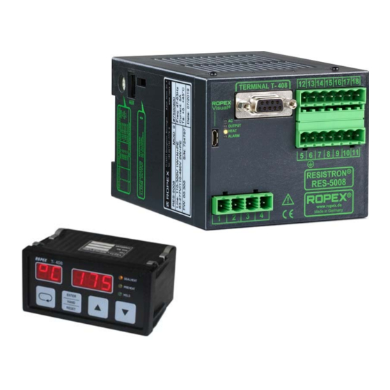
Commissioning and operation Commissioning and operation Device view ® RESISTRON Temperature Controller RES-5008: Circuit Display LEDs Terminal Coding and Slide switch Terminal plan USB interface Rating plate Connection terminals Terminal T-408-1: Rating plate Cable connection Indicator display Fastening hooks (4x) Operating keys Device configuration NOTE... - Page 21 300°C 3500ppm/K PC-CONFIGURATION 0 = Factory settings When the switch position “9” is selected, additional temperature ranges and alloys can be set through the ROPEX ® visualisation software ( section 9.22 "USB-interface for visualisation software ROPEXvisual " on page 45).
-
Page 22: Burning In And Changing The Heating Element
(factory setting) NOTE ROPEX recommends the configuration “Alarm relay contact opened by alarm” in combination with contactor Kb to switch off the load in the event of a fault. As a result, the interruption of the ®... - Page 23 8.3.2 The burn-in effect described here does not need to be considered if the manufacturer pre-treated the heating element for this purpose. The thermal pre-treatment is described as “burned in” at ROPEX in the Changing the heating element article text.
-
Page 24: Commissioning Rules
If the new heating element has another specification (e.g., heating element cross section, alloy), the application must be checked ( ROPEX-application report). If this specification was not taken into account in the application report, the application report must be updated in accordance with the new requirements. - Page 25 If the zeroing is unsuccessful, a corresponding error message is shown on the display of the T- 408-1 terminal and the red “ALARM” LED blinks slowly (1 Hz). Then the configuration of the regulator is not correct ( section 8.2 "Device configuration" on page 20, ROPEX application report). After the device configuration is correct, perform zeroing again.
-
Page 26: Device Functions
Lights up or blinks to indicate RES-5008 (red ALARM. www. ROPEX Made in Germany The LEDs display additional operating statuses of the regulator besides the functions in the above illustration. The operating states are shown in detail in the following table: Blinks slowly (1 Hz) -
Page 27: Display Image Of The T-408-1 Terminal
Device functions Terminal T-408-1: LED display, 5 characters ROPEX T-408 SEALHEAT PREHEAT Yellow LED: Heatung up/temp. control HOLD to set temperature active Yellow LED: PREHEAT active ENTER Green LED: Hold mode active HAND RESET “UP” and “DOWN” keys for setting values Press (<... -
Page 28: Menu Navigation
Device functions 9.2.3 Settings menu The required parameters are set in the Settings menu ( section 9.4 "Menu structure" on page 29) ROPEX T-408 SEALHEAT PREHEAT HOLD ENTER HAND RESET 9.2.4 Error message The fault diagnosis function of the controller is always active. A detected error is always reported in the form of an error message on the display (... -
Page 29: Menu Structure
Device functions Menu structure 1) AUTOCOMP: OFF Switch-on message 2) AUTOCOMP: ON °C Home position Sealing temperature Preheat temperature Autocal? Hold mode Autocal Autocomp? Autocomp Error Alarm Autocal? Autocal Version 2 RES-5008 Page 29... -
Page 30: Menu Items
Device functions Menu items Labelling Description Adjustment range °C Home position The current actual value is shown on the terminal's display. A manual heating process (to the adjusted sealing or preheating temperature) can be started by pressing the “HAND” button. [SealHeat] The desired sealing temperature (setpoint value) 0, 40 °C…Maximum temp. -
Page 31: Temperature Setting (Setpoint Specification)
START signal or pressing the “HAND” button. The setting range 1…39 °C is not available. Temperature display/Actual value output If the display is in the basic position “°C”, the ACTUAL temperature is shown. ROPEX T-408 SEALHEAT PREHEAT... - Page 32 Device functions ® In addition, the RESISTRON Temperature Controller RES-5008 delivers an analogue signal 0…10 VDC at the terminals 17+7. The analogue signal is proportional to the real ACTUAL temperature. RES-5008 Max. 5 mA Actual value output 0…10 VDC 0…10 VDC Temperature display e.g.
-
Page 33: Automatic Zero Calibration (Autocal)
Device functions With this, not only SETPOINT-ACTUAL comparisons can be made, but also other criteria can be evaluated, such as heat-up speed, reaching the setpoint in the specified time, cooling of the heating element, etc. Beyond that, malfunctions in the control circuit (loose contacts, contacting and wiring problems) and possibly mains faults can be observed very well at the display instrument. -
Page 34: Heating Up To The Sealing Temperature (Heat)
Device functions message “no2”. Heating up to the sealing temperature (HEAT) With the activation of the “START” signal (and the PREHEAT signal deactivated simultaneously), the device- internal target-actual comparison is enabled immediately and the heating element is heated up to the SETPOINT temperature. -
Page 35: Preheat
Device functions The PREHEAT signal is activated through a 24 VDC signal to the terminals 18+7. 24 VDC RES-5008 PREHEAT Max. 6 mA ≥ HIGH: 12 VDC PREHEAT (PREHEATING) ≤ LOW: 2 VDC CAUTION The heating to the preheat temperature takes place when the START and PREHEAT signals are activated. -
Page 36: Hold Mode
Device functions 9.11 Hold mode If the display of the terminal T-408-1 is in the basic position “°C”, the ACTUAL temperature is indicated. The properties of the display for the ACTUAL temperature can be changed in the menu item “HO” [HOld]. The following settings are possible: 1. -
Page 37: Temperature Unit Celsius/Fahrenheit
Device functions The different Hold modes are depicted in the following image: START- Signal 24 VDC ACTUAL- temperature ACTUAL display Hold OFF Hold On Hold Hold Hold On2 Hold Hold Sealing phase While the temperature value is displayed in Hold mode, the green “HOLD” LED at the terminal lights up. 9.12 Temperature unit Celsius/Fahrenheit NOTE... - Page 38 (e.g. a thermocouple). The measured temperature is transferred to the temperature controller by means of the ROPEX visualization software. The calculated temperature coefficient can be read off there. The temperature coefficient is only calculated in control mode (START signal active).
- Page 39 Device functions Reading back the calculated TCR value must be done during active control operation, i.e. during an active heating impulse, as the internal measured value of the current heatsealing band temperature is used for the calculation. Errors in the calculation of the temperature coefficient are reported with the value 0 (calculated temperature coef- ficient too low or no active control operation) or 65535 (calculated temperature coefficient too high).
-
Page 40: Measurement Impulse Duration
” on page 45). The measuring pulse extension can also be ordered as a modification from ROPEX ( section 15 "Modifications (MODs)" on page 60). The modification is then listed on the nameplate of the controller so that the technical change is visible. -
Page 41: Autocomp
Device functions In special sealing applications it may be necessary to counterbalance the phase shift between the U and I meas- urement signals, e.g. in case of very low-resistance short heating elements or heating elements with magnetic properties. The phase correction is executed with the “AUTOCOMP” function. The following settings are possible: 1. -
Page 42: Temperature Diagnosis
-10 K and +10 K, respectively. These values can be set separately from each other with the ROPEX visualisation software. After activation of the START signal, if the ACTUAL temperature is found within the specified tolerance band, the temperature diagnosis is switched on. -
Page 43: Heat-Up Time Monitoring
Device functions 9.16 Heat-up time monitoring An additional heat-up time monitoring can be activated with the ROPEX visualisation software ( section 9.22 ® "USB-interface for visualisation software ROPEXvisual " on page 45). ® The heating-up time monitoring is activated when the START signal is switched on. The RESISTRON Temperature Controller RES-5008 then monitors the time till the ACTUAL temperature reaches 95 % of the SETPOINT temperature. -
Page 44: Maximum Measurement Pause
For these cases the maximum measuring pause can be shortened with the parameter „Maximum measurement pause“. NOTE The user can only set the maximum measurement pause with the ROPEX visualisation soft- ® ware ( Chapter 9.20 “USB interface for the visualisation software ROPEXvisual ”... -
Page 45: Booster Connection
USB-interface for visualisation software ROPEXvisual A USB interface (type micro-USB) is available for system diagnosis and process visualisation. A data connection ® can be built up with the ROPEX visualisation software ROPEXvisual over this USB interface. 12 13 14 15 16 17 18... -
Page 46: Aux Interface
Permanent records of the sealing parameters cannot be created with this. The recording of the sealing parameters or status bits must be done within the machine control. A separate document is available for the ROPEX-visualisation soft- ®... - Page 47 • An error message can be reset by applying the “RESET” signal or switching the controller off and on. The error message is reset only when the button is released. ROPEX T-408 SEALHEAT PREHEAT...
-
Page 48: Error Messages
Temperature Controller RES-5008 displays 13 voltage levels for error diagnosis via the actual value output. Internally in the regulator, the error messages are differentiated in even more detail. 3-digit error numbers are also displayed with the ROPEX-Visualisation software ( section 9.22 "USB-interface for visualis- ®... - Page 49 Device functions Part 1 of 3: Error messages (faults) NOTE: The specified error messages are output as faults: • Actual value output displays constant error voltage • Alarm LED lights up continuously • Alarm relay is active Actual Measure during value Measure during initial machine operation,...
- Page 50 Device functions Part 1 of 3: Error messages (faults) NOTE: The specified error messages are output as faults: • Actual value output displays constant error voltage • Alarm LED lights up continuously • Alarm relay is active Actual Measure during value Measure during initial machine operation,...
- Page 51 Device functions Part 2 of 3: Error messages (warnings) NOTE: The specified error messages are first output as warnings: • Actual value output changes between two values • Alarm LED blinks quickly • Alarm relay is not active After activation of the START signal, the output occurs as a fault: •...
- Page 52 Device functions Part 3 of 3: Error messages (warnings) NOTE: The specified error messages are first output as warnings: • Actual value output changes between two values • Alarm-LED blinks slowly • Alarm relay is not active After activation of the START signal, the output occurs as a fault •...
-
Page 53: Error Areas And Causes
Device functions 9.26 Error areas and causes Temperature controller HARDWARE Explanations of the possible error causes can be taken from the following table. Error Explanations Possible causes range Interruption of the load circuit after - Wire break, heating element break the U pickup point - Contacting at the heating element defective... -
Page 54: Measures In The Event Of An Error
The control can function properly only if all components are matched with one another. The ROPEX application report fulfils exactly this task and should therefore be fully implemented. If the system is not designed according to the ROPEX application report, or if the martinal conditions change, this can lead to bad control or even malfunctions. -
Page 55: Factory Settings
Then carry out the AUTOCAL function and repeat the five steps listed above to locate the loose contact. If the measures described has not led to success, please contact us directly (info@ropex.de) and send the fol- lowing information to: •... -
Page 56: Maintenance
Maintenance Measurement Measurement impulse duration: 1.7 ms impulse duration Automatic AUTOCOMP: off Phase correction (AUTOCOMP) Temperature Temperature diagnosis: deactivated diagnosis Heat-up time Heat-up time monitoring: deactivated monitoring Maintenance The controller does not require any special maintenance. Regular checking and retightening of the connection terminals is recommended. -
Page 57: Technical Data
Secondary current I : 30…500 A with current transformer PEX-W4/W5 (lower currents: Secondary cables lead through the current transformer several times, higher currents with a load resistor) The dimensioning is made in the ROPEX application report. Version 2 RES-5008 Page 57... - Page 58 Heating element type In addition to the setting through the rotary encoder switch, the setting for and temperature the temperature range and temperature coefficient can be made via the ROPEX range visualisation software ( section 9.22 "USB-interface for visualisation software ®...
-
Page 59: Dimensions
Dimensions Connecting cable Rigid or flexible; 0.2…2.5 mm² (AWG 24…12) Through pluggable terminals Type/cross-sections Pluggable terminals: Tightening torque: 0.5…0.6 Nm (Screwdriver: SZS 0.6x3.5 mm) CAUTION If ferrules are used, they must be crimped in accordance with DIN 46228 and IEC/EN 60947-1. Otherwise, correct electrical contact in the termi- nals is not guaranteed. -
Page 60: Modifications (Mods)
Modifications (MODs) Terminal T-408-1: front panel panel cutout o 5mm +0.8 +0.6 x 45 55.0 56.0 outline dimensions front frame Modifications (MODs) ® The RESISTRON Temperature Controller RES-5008 is suitable for very many sealing applications due to its uni- versal design. ®... -
Page 61: How To Order
How to order How to order Controller RES-5008 Art. no. 7500800 Scope of delivery: Regulator with plug-in terminal parts (without transformer) Terminal T-408-1 Art. no. 885441 Scope of delivery: Terminal with fixing clips Sub-D-connection cable 2 m: Art. no. 884202 5 m: Art. - Page 62 50520: Continuous current 50 A, 520 VAC, art. no. 885509 (with UL and CSA certification) Impulsetransformer For design and order specifications, see ROPEX application report Design in accordance with EN 61558 in IP00 Available with UL certifications and thermal switch, if necessary.
-
Page 63: Index
Index Index Numbers Heating element type Heat-up time monitoring 24 VDC power supply High altitude Humidity Actual value output Alarm output Impulse transformer Alarm relay Installation Alloy Installation rules Ambient conditions Ambient temperature Application report AUTOCAL LEDs AUTOCOMP Line filter Automatic phase correction Line frequency Automatic zero calibration... - Page 64 Index Undervoltage detection TCR Calculator USB interface Temperature coefficient Temperature diagnosis Temperature display Temperature range Visualisation software Temperature regulation Temperature setting Temperature unit Wiring Thermal impulse process Transformer Page 64 RES-5008 Version 2...
Need help?
Do you have a question about the RESISTRON RES-5008 and is the answer not in the manual?
Questions and answers