Advertisement
Quick Links
Advertisement

Subscribe to Our Youtube Channel
Related Manuals for Mecmesin Basic Force Gauge-HS Mk3


Summary of Contents for Mecmesin Basic Force Gauge-HS Mk3
-
Page 3: Table Of Contents
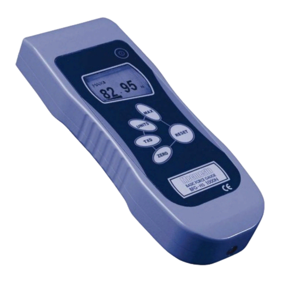
The Mecmesin BFG-HS is a member of a series of highly versatile display units. By using the latest integrated circuit technology it has been possible to produce an... -
Page 4: Powering The Gauge
Powering the Gauge Fitting and charging of The BFG-HS is supplied with a set of 5 Nickel Metal Hydride rechargeable batteries AAA rechargeable batteries. For safety reasons during transportation the batteries are shipped discharged. To obtain maximum battery life we recommend that you charge them with the charger/adaptor supplied for at least 14 - 16 hours when you first receive the BFG-HS. -
Page 5: Using The Gauge
Excessive torque can damage the loadcell. Mounting to a test stand On the rear of the gauge there are two M5 threaded holes, which can be used for mounting the gauge to a Mecmesin test stand. Each Mecmesin test stand is supplied with a dedicated ‘dovetailed mounting bracket’... - Page 6 After the self test, providing no load has been applied to the Please note that a BFG-HS instrument, the display will show all zeroes. This is because measuring very low forces may the gauge re-zeroes itself during the self test routine. not show zero if it is moved during the self test routine.
- Page 7 A load indicator bar alerts the operator to how much load has been applied to the transducer. As the load approaches the maximum rating of the transducer, the indicator bar changes appearance when above approx. 80% of the rated capacity. This warns the operator that steps should be taken to prevent excessive load being applied.
- Page 8 Fig. 3a Dual Max max tension reading max compression reading Load currently applied to load cell Max Tension Press the MAX key again and the display will show the maximum tensile force identified by the symbol. Fig. 3b max tension reading Max Compression Press the MAX key again and the display will show the...
- Page 9 "Normal" mode Press the MAX key again and the word MAX has now disappeared from the display. The display will now indicate forces applied in both directions as they are applied to the transducer and maintain a "running" display. Press the RESET key to clear both maximum registers and prepare for detecting the next maximum readings.
-
Page 10: Optional Settings
Optional Settings Backlit It is possible to activate a backlight on the BFG-HS display. Display Press and hold RESET whilst powering up the BFG-HS with key. The backlight is now operating. Please note that battery consumption is doubled when using the backlight. - Page 11 Fig. 4 upper value = offset when last calibrated lower value = offset currently present on gauge If the % offset is between 5% - 10% please contact your supplier to arrange a recalibration of your BFG-HS. If the % offset is greater than 10% please contact your supplier to arrange for a loadcell replacement.
-
Page 12: Dimensions
Dimensions 30.9mm Front View Side View LOADCELL STUD: THREAD = M6 x 1.0p 77mm OPTIONAL DOVETAIL BRACKET FOR MOUNTING ON TEST STANDS MAXIMUM SIZE SCREWS = M5x10 SOCKET CAP HEAD SCREW Rear View Pin Out: Analogue Output RS232 Transmit RS232 Receive Mitutoyo Clock Output Mitutoyo Ready Output not used... -
Page 13: Bfg-Hs Specification Table
BFG-HS Specification Table Range & Resolution Model no: kg-f oz-f lb-f BFG-HS 10 10,000 x 2 10 x 0.002 1,000 x 0.2 1 x 0.0002 35 x 0.01 2.2 x 0.0005 BFG-HS 50 50,000 x 10 50 x 0.01 5,000 x 1 5 x 0.001 180 x 0.05 11 x 0.002... - Page 16 ÿ›·cÕ‡ßgLYßž S.I. Instruments ±x^.»PÑ›Ni«Æ 256 South Rd. Hilton ´çJ>·w¬ËàXà⊜ South Australia 5033 (˜b&’†üušÕ– Ph (08) 8352 5511 wi¤Ë™Ögk}xçÐ-ñ ¥˙ ÞS¾Z$ú[ info@si-instruments.com.au âoÆÈ www.si-instruments.com.au y3j6# $”khì.B8««*mö&Ž É ˘/‰íìP5ßp¦s)
Need help?
Do you have a question about the Basic Force Gauge-HS Mk3 and is the answer not in the manual?
Questions and answers