Tektronix KEITHLEY SourceMeter 2600B Series User Manual
Hide thumbs
Also See for KEITHLEY SourceMeter 2600B Series:
- Reference manual (834 pages) ,
- Reference manual (946 pages)

Related Manuals for Tektronix KEITHLEY SourceMeter 2600B Series


Summary of Contents for Tektronix KEITHLEY SourceMeter 2600B Series
- Page 1 tek.com/keithley Series 2600B System SourceMeter Instrument ® User's Manual 2600BS-900-01 Rev. A August 2021 *P2600BS-900-01A* 2600BS-900-01A...
- Page 2 Series 2600B ® System SourceMeter instrument User's Manual...
- Page 3 © 2021, Keithley Instruments, LLC Cleveland, Ohio, U.S.A. All rights reserved. Any unauthorized reproduction, photocopy, or use of the information herein, in whole or in part, without the prior written approval of Keithley Instruments, LLC, is strictly prohibited. These are the original instructions in English. and TSP-Link are trademarks of Keithley Instruments, LLC.
- Page 4 Safety precautions The following safety precautions should be observed before using this product and any associated instrumentation. Although some instruments and accessories would normally be used with nonhazardous voltages, there are situations where hazardous conditions may be present. This product is intended for use by personnel who recognize shock hazards and are familiar with the safety precautions required to avoid possible injury.
- Page 5 For safety, instruments and accessories must be used in accordance with the operating instructions. If the instruments or accessories are used in a manner not specified in the operating instructions, the protection provided by the equipment may be impaired. Do not exceed the maximum signal levels of the instruments and accessories. Maximum signal levels are defined in the specifications and operating information and shown on the instrument panels, test fixture panels, and switching cards.
-
Page 6: Table Of Contents
Table of contents Introduction ......................1-1 Welcome ..........................1-1 Extended warranty ....................... 1-1 Contact information ......................1-1 Customer documentation ..................... 1-2 Product software and drivers ....................1-3 General ratings ........................1-4 Installation ........................ 2-1 Introduction .......................... 2-1 Cooling vents ........................2-1 Turning the instrument on and off .................. - Page 7 Table of contents Series 2600B System SourceMeter® instrument User's Manual Change the IP configuration through the web interface ............3-37 Set the instrument password ....................3-38 Using the virtual front panel..................... 3-38 View buffer data using the web interface ................3-39 Download reading buffer data using the web interface ............
- Page 8 Series 2600B System SourceMeter® instrument User's Manual Table of contents Front-panel tests ........................5-3 Keys test ........................... 5-3 Display patterns test ........................5-3 Upgrading the firmware ......................5-4 Using TSB to upgrade the firmware ..................5-5 Displaying the serial number ....................5-6 Next steps .........................
-
Page 9: Introduction
If you have any questions after you review the information in this documentation, please contact your local Keithley Instruments office, sales partner, or distributor. You can also call the Tektronix corporate headquarters (toll-free inside the U.S. and Canada only) at 1-800-833-9200. For worldwide... -
Page 10: Customer Documentation
Section 1: Introduction Series 2600B System SourceMeter® instrument User's Manual Customer documentation The documentation for the 2600B includes a Quick Start Guide, User's Manual, and Reference Manual. A Quick Start Guide is provided as a hard copy with the instrument. You can also access it from tek.com/keithley as an Adobe Acrobat PDF file. -
Page 11: Product Software And Drivers
Series 2600B System SourceMeter® instrument User's Manual Section 1: Introduction Product software and drivers Go to the Product Support and Downloads web page (tek.com/product-support) to download drivers and software for your instrument. Available drivers and software include: • KickStart Software: Enables quick test setup and data visualization when using one or more instruments. -
Page 12: General Ratings
Section 1: Introduction Series 2600B System SourceMeter® instrument User's Manual General ratings Category Specification Supply voltage range 100 V ac to 240 V ac, 50 Hz or 60 Hz (autosensing), 240 VA maximum Input and output connections Front panel (on page 3-1) and Rear panel (on page 3-5) Environmental conditions... -
Page 13: Installation
Section 2 Installation In this section: Introduction ................2-1 Cooling vents ................2-1 Turning the instrument on and off ..........2-2 Placing a 2600B in standby ............2-3 Warmup period ................. 2-3 Line frequency configuration ............ 2-4 System information ..............2-4 Introduction This section provides the information you need to install the 2600B, make communications connections, and power up the instrument. -
Page 14: Turning The Instrument On And Off
Section 2: Installation Series 2600B System SourceMeter® instrument User's Manual If high power dissipation equipment is rack mounted next to the 2600B, it could cause excessive heating. To produce specified 2600B accuracies, maintain the specified ambient temperature around the surfaces of the 2600B. In rack configurations with convection cooling only, proper cooling practice places the hottest non-precision equipment (for example, the power supply) at the top of the rack away from and above precision equipment (such as the 2600B). -
Page 15: Placing A 2600B In Standby
Series 2600B System SourceMeter® instrument User's Manual Section 2: Installation Hazardous voltages may be present in the test system. To prevent injury or death, remove power from the instrument or test system and discharge any energy storage components (for example, capacitors or cables) before changing any connections that might allow contact with an uninsulated conductor. -
Page 16: Line Frequency Configuration
Section 2: Installation Series 2600B System SourceMeter® instrument User's Manual Line frequency configuration The factory configures the 2600B to detect the power line frequency automatically at each power-up. This detected line frequency (either 50 Hz or 60 Hz) is used for aperture (NPLC) calculations. In noisy environments, you can manually configure the instrument to match the actual line frequency. -
Page 17: Instrument Description
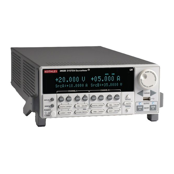
Section 3 Instrument description In this section: Controls, indicators, and connectors ........3-1 Menu overview ............... 3-12 Beeper ................... 3-21 Displayed error and status messages ........3-21 Display operations ..............3-22 Connecting the USB flash drive ..........3-34 Using the web interface ............3-35 Controls, indicators, and connectors 2600B controls, indicators, and the USB port are on the front panel... - Page 18 Section 3: Instrument description Series 2600B System SourceMeter® instrument User's Manual Figure 2: Front panel of two-channel SMU (2602B, 2604B, 2612B, 2614B, 2634B, and 2636B) 1. Power switch, display and configuration keys Toggles between the source-measure displays and the user message mode. Configures a function or operation.
- Page 19 Series 2600B System SourceMeter® instrument User's Manual Section 3: Instrument description Special operation Loads a test for execution (FACTORY, USER, or SCRIPTS). LOAD Runs the last selected factory or user-defined test. Accesses reading buffers and makes readings: STORE ▪ TAKE_READINGS: Use to make readings and store them in a reading buffer. ▪...
- Page 20 Section 3: Instrument description Series 2600B System SourceMeter® instrument User's Manual 4. Cursor keys Use the CURSOR keys to move the cursor left or right. When the cursor is on the source or compliance value digit, press the navigation wheel to enter edit mode, and turn the navigation wheel to edit the value.
-
Page 21: Rear Panel
Series 2600B System SourceMeter® instrument User's Manual Section 3: Instrument description 8. Display indicators (not shown) The items listed below represent the possible display indicators and their meanings. Indicator Meaning Remote (4-wire) sense is selected Source or measure autorange is selected AUTO Instrument is in editing mode EDIT... - Page 22 Section 3: Instrument description Series 2600B System SourceMeter® instrument User's Manual Figure 4: 2602B and 2612B rear panel Figure 5: 2604B rear panel 2600BS-900-01 Rev. A / August 2021...
- Page 23 Series 2600B System SourceMeter® instrument User's Manual Section 3: Instrument description Figure 6: 2614B rear panel Figure 7: 2634B rear panel 2600BS-900-01 Rev. A / August 2021...
- Page 24 Section 3: Instrument description Series 2600B System SourceMeter® instrument User's Manual Figure 8: 2635B rear panel Figure 9: 2636B rear panel 2600BS-900-01 Rev. A / August 2021...
- Page 25 Series 2600B System SourceMeter® instrument User's Manual Section 3: Instrument description 1. SMU connector Channel A This connector provides input/output connections for HI 2601B, 2602B, 2604B, 2611B, 2612B, 2614B and LO, sense (S HI/S LO), and guard (G). Connections are as follows: LO = LO S LO = Sense LO G = Guard...
- Page 26 Section 3: Instrument description Series 2600B System SourceMeter® instrument User's Manual 3. Digital I/O Female DB-25 connector. Use a cable equipped with a 2601B, 2602B, 2611B, 2612B, 2635B, 2636B male DB-25 connector (L-com part number CSMN25MF-5). Pins provided: Fourteen digital input or output pins, seven GND pins, and three +5 V pins.
- Page 27 Series 2600B System SourceMeter® instrument User's Manual Section 3: Instrument description 7. Ground 2601B, 2602B, 2604B, 2611B, 2612B, 2614B Ground terminal for connection output HI or LO to chassis ground. Ground screw for connections to chassis ground. Triaxial connector on ground module. 2635B Screw terminal connector on ground module.
-
Page 28: Menu Overview
Section 3: Instrument description Series 2600B System SourceMeter® instrument User's Manual Menu overview The following topics describe how to work with the front-panel menus. Menu navigation To navigate through the menus and submenus, the 2600B must not be in edit mode (the EDIT indicator is not illuminated). - Page 29 Series 2600B System SourceMeter® instrument User's Manual Section 3: Instrument description Figure 10: Main menu tree 1 Mutually exclusive 2 TSP-Link is not available on the 2604B, 2614B, and 2634B 3 DIGOUT is not available on the 2604B, 2614B, and 2634B The following table contains descriptions of the main menu options and cross-references to related information.
- Page 30 Section 3: Instrument description Series 2600B System SourceMeter® instrument User's Manual Menu selection Description For more information, see: SCRIPT Saves and recalls user scripts Series 2600B Reference Manual, “Manage scripts” - LOAD Loads scripts into nonvolatile memory - SAVE Saves scripts Series 2600B Reference Manual, “Saved Saves and recalls user and factory setup options SETUP...
- Page 31 Series 2600B System SourceMeter® instrument User's Manual Section 3: Instrument description Configuration menus The configuration menu structure is summarized in the following figures. More detailed information follows the figures. For directions on navigating the menu, see Menu navigation (on page 3-12). For other menu items, see Main menu (on page 3-12).
- Page 32 Section 3: Instrument description Series 2600B System SourceMeter® instrument User's Manual Figure 12: CONFIG menu tree COMMON menu (models with two SMUs) 1 Enter a value 2 Replace X with A for SMU Channel A (such as in CHANA-BUF) or a B for SMU Channel B (such as in CHANB-BUF) Press the EXIT key to return to a previous menu.
- Page 33 Series 2600B System SourceMeter® instrument User's Manual Section 3: Instrument description Figure 13: CONFIG menu tree (models with a single SMU) 1 Select a value 2 Enter a value 3 Model 2635B only Press the EXIT key to return to a previous menu. 2600BS-900-01 Rev.
- Page 34 Section 3: Instrument description Series 2600B System SourceMeter® instrument User's Manual The following table contains descriptions of the configuration menus and cross-references to related information. To select a menu for single SMU instruments, press the CONFIG key and then the front-panel key associated with the menu (see the description column in the following table).
-
Page 35: Setting Values
Series 2600B System SourceMeter® instrument User's Manual Section 3: Instrument description Setting values Through the front panel, you can adjust a value using either the Navigation wheel method or Numeric entry method (using the keypad). Setting a value To set a value using the navigation wheel method: 1. - Page 36 Section 3: Instrument description Series 2600B System SourceMeter® instrument User's Manual Setting source and compliance values When the 2600B is in the edit mode (EDIT indicator is on), the editing controls are used to set source and compliance values. Note that when you edit the source value, source autoranging is turned off and remains off until you turn it on again.
-
Page 37: Beeper
Series 2600B System SourceMeter® instrument User's Manual Section 3: Instrument description Beeper The 2600B includes a beeper. When it is enabled, a beep indicates one of the following actions occurred: • A front-panel key was pressed: A short beep, similar to a key click, is issued. •... -
Page 38: Display Operations
Section 3: Instrument description Series 2600B System SourceMeter® instrument User's Manual Display operations This section describes methods for using the display and determining what is displayed. Display mode Use the DISPLAY key to scroll through the various display modes shown in the figure below. Refer to Display operations (on page 3-22) for more information about the display. -
Page 39: Display Functions And Attributes
Series 2600B System SourceMeter® instrument User's Manual Section 3: Instrument description Display functions and attributes The display functions and attributes for the front panel are described in this section. The following table lists each display function and attribute (in alphabetical order) and cross references it to the section topic where the function or attribute is explained. -
Page 40: Display Features
Section 3: Instrument description Series 2600B System SourceMeter® instrument User's Manual Display features You can set the front-panel display to display the units of measure, number of digits, and customized text messages for your applications. Display screen The front panel displays source-measure values and readings or user-defined messages. The display screen options include: •... -
Page 41: Display Messages
Series 2600B System SourceMeter® instrument User's Manual Section 3: Instrument description Display trigger wait and clear To set the instrument to wait for the front-panel TRIG key to be pressed, send the display.trigger.wait() function. To clear the trigger event detector, send the display.trigger.clear() function. - Page 42 Section 3: Instrument description Series 2600B System SourceMeter® instrument User's Manual Cursor position When displaying a message, the cursor position determines where the message starts. On power-up, the cursor is positioned at row 1, column 1 (see the following figure). At this cursor position, a user-defined message is displayed on the top row (row 1).
- Page 43 Series 2600B System SourceMeter® instrument User's Manual Section 3: Instrument description The following programming example illustrates how to position the cursor on row 2, column 1, and then read the cursor position: display.setcursor(2, 1) row, column = display.getcursor() print(row, column) Output: 2.00000e+00 1.00000e+00 Displaying text messages...
- Page 44 Section 3: Instrument description Series 2600B System SourceMeter® instrument User's Manual The following programming example illustrates how to use the $N and $B character codes to display the message Test in Process on the top line and the blinking message Do Not Disturb on the bottom line: display.clear() display.settext("Test in Process $N$BDo Not Disturb")
-
Page 45: Input Prompting
Series 2600B System SourceMeter® instrument User's Manual Section 3: Instrument description Sending the command without the row parameter returns both lines of the display. The $N character code is included to show where the top line ends and the bottom line begins. The $N character code is returned even if embellished is set to false. - Page 46 Section 3: Instrument description Series 2600B System SourceMeter® instrument User's Manual Parameter value prompting You can use the display.inputvalue() and display.prompt() functions to create an editable input field on the user screen at the present cursor position. The display.inputvalue() function uses the user screen at the present cursor position. Once the command is finished, it returns the user screen to its previous state.
-
Page 47: Indicators
Series 2600B System SourceMeter® instrument User's Manual Section 3: Instrument description The following programming example illustrates how to prompt the operator to enter a source voltage value for SMU A: display.clear() value = display.prompt("0.00", "V", "Enter source voltage") display.screen = display.SMUA smua.source.levelv = value The script pauses after displaying the prompt message and waits for the operator to enter the voltage level. -
Page 48: Local Lockout
Section 3: Instrument description Series 2600B System SourceMeter® instrument User's Manual For example, assume the returned bitmap value is 34061. The binary equivalent of this value is as follows: 1000010100001101 For the above binary number, the following bits are set to 1: 16, 11, 9, 4, 3, and 1. Using the table, the following indicators are on: REL, REM, EDIT, AUTO, 4W, and FILT. - Page 49 Series 2600B System SourceMeter® instrument User's Manual Section 3: Instrument description Adding USER TESTS menu entries You can use the following function in either of two ways to add an entry into the USER TESTS menu: display.loadmenu.add(displayname, code) display.loadmenu.add(displayname, code, memory) Where: displayname The name string that is added to the USER TESTS menu.
-
Page 50: Running A Test From The Front Panel
Section 3: Instrument description Series 2600B System SourceMeter® instrument User's Manual Deleting USER TESTS menu entries You can use the following function to delete an entry from the front-panel USER TESTS menu: display.loadmenu.delete(displayname) Where: displayname Name to delete from the menu. The following programming example removes the entry named Part1 from the front-panel USER TESTS menu: display.loadmenu.delete("Part1") -
Page 51: Using The Web Interface
Series 2600B System SourceMeter® instrument User's Manual Section 3: Instrument description Using the web interface If you are connected to the 2600B using LAN communications, you can use an internet browser to connect to the instrument through the 2600B web interface. The LXI web interface allows you to change settings and control your instrument through the web interface. -
Page 52: Web Interface Welcome Page
Section 3: Instrument description Series 2600B System SourceMeter® instrument User's Manual To access the web interface: 1. Open a web browser on the host computer. 2. Enter the IP address of the instrument in the web browser address box. For example, if the instrument IP address is 192.168.1.101, enter 192.168.1.101 in the browser address box. -
Page 53: Use The Id Button To Identify The Instrument
Series 2600B System SourceMeter® instrument User's Manual Section 3: Instrument description Use the ID button to identify the instrument If you have a bank of instruments, you can select the ID button to determine which instrument you are communicating with. The ID button is below the menu on every page of the web interface. -
Page 54: Set The Instrument Password
Section 3: Instrument description Series 2600B System SourceMeter® instrument User's Manual Set the instrument password You can change the instrument password from the web interface. The instrument password is used for access to the instrument from any remote interface. When password usage is enabled by the localnode.passwordmode command, you must supply a password to change the configuration or to control an instrument a remote command interface. -
Page 55: View Buffer Data Using The Web Interface
Series 2600B System SourceMeter® instrument User's Manual Section 3: Instrument description Figure 18: Virtual front panel View buffer data using the web interface You can view the data in the reading buffers on the Reading Buffers page of the Virtual Front Panel web page. -
Page 56: Download Reading Buffer Data Using The Web Interface
Section 3: Instrument description Series 2600B System SourceMeter® instrument User's Manual Figure 19: Web interface Reading Buffers page Download reading buffer data using the web interface You can download reading buffer data to a .csv file from the Reading Buffers page of the web interface. -
Page 57: Using Tsb Embedded
Series 2600B System SourceMeter® instrument User's Manual Section 3: Instrument description Using TSB Embedded TSB Embedded is a script management tool that is available through the web interface of the instrument. You can use TSB Embedded to create, modify, and save test scripts, and to send individual commands. - Page 58 Section 3: Instrument description Series 2600B System SourceMeter® instrument User's Manual Figure 20: LXI Event Log The timestamp, event identifier, IP address, and the domain name identify the incoming and outgoing LXI trigger packets. The following table provides detailed descriptions for the columns in the event log.
- Page 59 Series 2600B System SourceMeter® instrument User's Manual Section 3: Instrument description Event log descriptions Column title Description Example Each instrument maintains independent Sequence sequence counters: ▪ One for each combination of UDP multicast network interface and UDP multicast destination port ▪...
-
Page 60: Help
Section 3: Instrument description Series 2600B System SourceMeter® instrument User's Manual The string displays the same information as the web interface. Commas separate the fields. The fields output in the following order: • Received time (UTC time) • Event ID •... -
Page 61: Operation
Section 4 Operation In this section: Basic operation ................ 4-1 Source-measure capabilities ............ 4-1 Limits ..................4-2 Sink operation ................4-5 DUT test connections ............... 4-6 Front-panel source-measure procedure ......... 4-28 Sense mode selection ............4-30 Output-off modes ..............4-31 Basic operation For the Models 2611B, 2612B, 2614B, 2634B, 2635B, and 2636B, hazardous voltages may be present on all output and guard terminals. -
Page 62: Voltage And Current
Section 4: Operation Series 2600B System SourceMeter® instrument User's Manual Voltage and current The following table lists the source and measure limits for the voltage and current functions. The full range of operation is explained in “Operating boundaries” in the Series 2600B Reference Manual. Source-measure capabilities 2601B, 2602B, 2604B 2611B, 2612B, 2614B... - Page 63 Series 2600B System SourceMeter® instrument User's Manual Section 4: Operation The limit operation of the instrument changes dependent on the source mode (current or voltage), load, and the configured limits (current, voltage, and power). It is important to distinguish both the current and voltage limits from the power limit.
-
Page 64: Setting The Limit From The Front Panel
Section 4: Operation Series 2600B System SourceMeter® instrument User's Manual Setting the limit from the front panel To set the limit for a single-channel instrument (2601B, 2611B, or 2635B) or the single-channel display mode of a two-channel instrument (2602B, 2604B, 2612B, 2614B, 2634B, or 2636B): 1. -
Page 65: Sink Operation
Series 2600B System SourceMeter® instrument User's Manual Section 4: Operation The following programming example illustrates how to print the limit state: print(smua.source.compliance) A returned value of true indicates one of these things: • If the instrument is configured as a current source, the voltage limit has been reached •... -
Page 66: Setting The Sink Mode Using The Front Panel
Section 4: Operation Series 2600B System SourceMeter® instrument User's Manual Setting the sink mode using the front panel To enable or disable the sink mode from the front panel: 1. Press the CONFIG key and then the SRC key. 2. Select V-SOURCE. 3. - Page 67 Series 2600B System SourceMeter® instrument User's Manual Section 4: Operation The fundamental source-measure configurations for the 2600B are shown in the following figures. When sourcing voltage, you can measure current or voltage, as shown in the following figure. Figure 21: Fundamental source-measure configurations: Source V Current meter Voltage source −...
-
Page 68: Input/Output Connectors
Section 4: Operation Series 2600B System SourceMeter® instrument User's Manual Input/output connectors The 2600B uses screw terminal connectors or triaxial connectors for input and output connections to devices under test (DUTs). The 2601B, 2602B, 2604B, 2611B, 2612B, and 2614B use screw terminal connectors. - Page 69 Series 2600B System SourceMeter® instrument User's Manual Section 4: Operation Figure 23: Input/output connectors Input/output LO and chassis ground As shown in the following figures, SMU input/output LOs are available at the rear panel terminal blocks. Input/output LOs are not connected between channels and are electrically isolated from chassis ground.
- Page 70 Section 4: Operation Series 2600B System SourceMeter® instrument User's Manual Figure 24: Models 2602B, 2604B, 2612B, and 2614B input/output LO and chassis ground terminals (2601B and 2611B similar) 1 Captive screw. Each terminal block uses two captive screws to secure it to the rear panel. Figure 25: Models 2634B and 2636B input/output and chassis ground terminals (Model 2635B similar) For the 2601B, 2602B, 2604B, 2611B, 2612B, and 2614B, there is a low-noise chassis ground...
- Page 71 Series 2600B System SourceMeter® instrument User's Manual Section 4: Operation The FVR, shown in the following figure, isolates the SMUs from high frequencies that may be present on the chassis of the 2600B. As frequencies on the chassis increase, the resistance of the FVR increases to dampen its effects.
-
Page 72: 2-Wire Local Sensing Connections
Section 4: Operation Series 2600B System SourceMeter® instrument User's Manual When connecting to 2611B, 2612B, 2614B, 2634B, 2635B, and 2636B SMU outputs using cables that are not rated for voltages above 42 V, such as the 2600-ALG-2, you must disable the high voltage output by using the INTERLOCK function as defined in Interlock (on page... - Page 73 Series 2600B System SourceMeter® instrument User's Manual Section 4: Operation When sourcing voltage with remote sense, the instrument relies on the voltage detected with the sense lines to provide the proper closed-loop control of its output voltage and to properly limit the voltage across the device-under-test.
-
Page 74: Contact Check Connections
Section 4: Operation Series 2600B System SourceMeter® instrument User's Manual Contact check connections The contact check function prevents measurement errors due to excessive resistance in the source or sense leads. See Contact check measurements (on page 4-14) for operation. Contact check requires both source and sense connections. Refer to 4-wire remote sensing connections (on page 4-12) for the connection scheme. - Page 75 Series 2600B System SourceMeter® instrument User's Manual Section 4: Operation smuX.source.offlimiti is ignored and the effective current limit depends on what the channel is sourcing when it is turned off. If the channel is sourcing: • Voltage: The current limit is determined by smuX.source.limiti. •...
-
Page 76: Guarding And Shielding
Section 4: Operation Series 2600B System SourceMeter® instrument User's Manual Guarding and shielding You can optimize source-measure performance and safety with the effective use of guarding and shielding (noise and safety shields). Safety shield A safety shield must be used whenever hazardous voltages (>30 V , 42 V ) will be PEAK... - Page 77 Series 2600B System SourceMeter® instrument User's Manual Section 4: Operation Figure 31: Safety shield for hazardous voltage combining two 2601B, 2602B, or 2604B channels 1 Chassis 2 Chassis screw 3 Device under test (DUT) 4 Protective earth (safety ground) 5 Equivalent schematic 6 Metal safety shield For the 2611B, 2612B, 2614B, 2634B, 2635B, and 2636B, the maximum output voltage for a channel is 220 V, which is considered hazardous and requires a safety shield.
- Page 78 Section 4: Operation Series 2600B System SourceMeter® instrument User's Manual Figure 32: Model 2611B, 2612B, or 2614B safety shield for hazardous voltage test circuit connections 1 Chassis 2 Chassis screw 3 Device under test (DUT) 4 Protective earth (safety ground) 5 Equivalent schematic 6 Metal safety shield 4-18...
- Page 79 Series 2600B System SourceMeter® instrument User's Manual Section 4: Operation Figure 33: Model 2634B, 2635B, or 2636B safety shield for hazardous voltage test circuit connections 1 Protective earth (safety ground) 2 Equivalent schematic 3 Metal safety shield 4 Device under test (DUT) 2600BS-900-01 Rev.
- Page 80 Section 4: Operation Series 2600B System SourceMeter® instrument User's Manual Guarding A driven guard is always enabled and provides a buffered voltage that is at the same level as the input/output HI voltage. The purpose of guarding is to eliminate the effects of leakage current (and capacitance) that can exist between HI and LO.
- Page 81 Series 2600B System SourceMeter® instrument User's Manual Section 4: Operation Noise shield Use a noise shield (see following figure) to prevent unwanted signals from being introduced into the test circuit. Low-level signals may benefit from effective shielding. The metal noise shield surrounds the test circuit and should be connected to LO, as shown.
- Page 82 Section 4: Operation Series 2600B System SourceMeter® instrument User's Manual Using shielding and guarding together The following figures show connections for a test system that uses a noise shield, a safety shield, and guarding. The guard shields are connected to the driven guard (labeled G or GUARD, depending on your model) of the SMU.
-
Page 83: Interlock
Series 2600B System SourceMeter® instrument User's Manual Section 4: Operation Interlock The interlock is available on the 2611B, 2612B, 2614B, 2634B, 2635B, and 2636B only. The digital I/O port provides the interlock line for use with a test fixture switch. When properly used, the output of the instrument turns off when the lid of the test fixture is opened. -
Page 84: Test Fixture
Section 4: Operation Series 2600B System SourceMeter® instrument User's Manual Figure 37: Using 2611B, 2612B, 2614B, 2634B, 2635B, and 2636B interlock 1 INTERLOCK pin (on DIGITAL I/O or INTERLOCK connector) pin 24 2 Read by firmware 3 To output stage 4 Coil resistance 5 Chassis ground 6 Rear panel... - Page 85 Series 2600B System SourceMeter® instrument User's Manual Section 4: Operation To provide protection from shock hazards, an enclosure should be provided that surrounds all live parts. Nonconductive enclosures must be constructed of materials that are suitably rated for flammability and the voltage and temperature requirements of the test circuit. Connect the enclosure of all metal test fixtures to protective earth (safety ground).
-
Page 86: Floating A Smu
Section 4: Operation Series 2600B System SourceMeter® instrument User's Manual Floating a SMU Using an external source in the test system may require that a 2600B source-measure unit (SMU) float off chassis earth ground. An example of such a test system is shown below, which includes an external voltage source. - Page 87 Series 2600B System SourceMeter® instrument User's Manual Section 4: Operation Figure 39: 2601B, 2602B, 2604B, 2611B, 2612B, or 2614B SMU connections 1 External source 2 Chassis 3 Output low connected to chassis 4 DUT 5 Source chassis connected to chassis earth ground through the power cord 6 Low-noise chassis ground banana jack 7 Chassis screw All measurement connections should be considered to be hazardous.
-
Page 88: Front-Panel Source-Measure Procedure
Section 4: Operation Series 2600B System SourceMeter® instrument User's Manual Front-panel source-measure procedure Use the following procedure to perform the basic source-measure operations of the 2600B SMU using the front panel. The following procedure assumes that the 2600B is already connected to the device under test (DUT), as explained in DUT test connections (on page 4-6). -
Page 89: Step 3: Select The Measurement Function And Range
Series 2600B System SourceMeter® instrument User's Manual Section 4: Operation Step 3: Select the measurement function and range To select measurement function and range: 1. If the instrument has two channels (2602B, 2604B, 2612B, 2614B, 2634B, or 2636B), press the DISPLAY key to place it in single-channel-display mode (if not already). -
Page 90: Sense Mode Selection
Section 4: Operation Series 2600B System SourceMeter® instrument User's Manual Sense mode selection You can set the sense mode to use 2-wire local sensing connections (on page 4-12) or 4-wire remote sensing connections (on page 4-12). The default sense setting is 2-wire local. Front-panel sense mode selection To check or change the voltage sense mode from the front panel: 1. -
Page 91: Output-Off Modes
Series 2600B System SourceMeter® instrument User's Manual Section 4: Operation Output-off modes Carefully consider and configure the appropriate output-off state, source function, and compliance limits before connecting the 2600B to a device that can deliver energy (for example, other voltage sources, batteries, capacitors, solar cells, or other 2600B instruments). -
Page 92: Output-Off Function
Section 4: Operation Series 2600B System SourceMeter® instrument User's Manual To configure the output-off mode from the front panel: 1. Press the CONFIG key. 2. Press the OUTPUT ON/OFF control. 3. Select OFF-STATE. 4. Select MODE. 5. Select the output-off mode: HI-Z (high-impedance), NORMAL, or ZERO. 6. -
Page 93: Output-Off Limits (Compliance)
Series 2600B System SourceMeter® instrument User's Manual Section 4: Operation Selecting the output-off function This setting is used only when the output is turned off and the source-measure unit (SMU) is in NORMAL output-off mode. To configure the output-off function from the front panel: 1. -
Page 94: Remote Programming Output-Off States Quick Reference
Section 4: Operation Series 2600B System SourceMeter® instrument User's Manual To set the current limit in NORMAL output-off mode remotely:* smuX.source.offlimiti = iValue To set the voltage limit in NORMAL output-off mode remotely:* smuX.source.offlimitv = vValue * smuX can be smua for channel A or smub for channel B Remote programming output-off states quick reference The content of the following table is a quick reference of commands for programming output-off states from a remote interface. -
Page 95: Maintenance
Section 5 Maintenance In this section: Introduction ................5-1 Line fuse replacement .............. 5-1 Fuse replacement ..............5-2 Front-panel tests ..............5-3 Upgrading the firmware ............5-4 Displaying the serial number ............ 5-6 Introduction This section describes routine maintenance of the instrument that an operator can perform. Line fuse replacement A fuse on the 2600B rear panel protects the power line input of the instrument. -
Page 96: Line Fuse Replacement
Section 5: Maintenance Series 2600B System SourceMeter® instrument User's Manual Figure 40: Fuse replacement Line fuse is in a similar location on the other 2600B models. To prevent injury, death, or instrument damage, use only the correct fuse type (see the Line Fuse table below). -
Page 97: Front-Panel Tests
Series 2600B System SourceMeter® instrument User's Manual Section 5: Maintenance Front-panel tests The front-panel tests test the functionality of the front-panel keys and the display. In the following procedures, highlight the menu item and press the ENTER key to select it. You can also select a menu item by pressing the navigation wheel. -
Page 98: Upgrading The Firmware
Section 5: Maintenance Series 2600B System SourceMeter® instrument User's Manual 5. To start the display test, press the ENTER key. There are three parts to the display test. Each time the ENTER key or the navigation wheel is pressed, the next part of the test sequence is selected. -
Page 99: Using Tsb To Upgrade The Firmware
Series 2600B System SourceMeter® instrument User's Manual Section 5: Maintenance To upgrade or downgrade the firmware using the front panel: 1. Turn the instrument power off. Wait a few seconds. 2. Turn the instrument power on. 3. Copy the firmware file to a USB flash drive. 4. -
Page 100: Displaying The Serial Number
Section 5: Maintenance Series 2600B System SourceMeter® instrument User's Manual To upgrade the firmware using Test Script Builder: 1. Start Test Script Builder. 2. On the Instrument Console toolbar, click the Open Instrument icon. Figure 41: Open Instrument icon 3. Select your instrument from the Select Instrument dialog box. 4. -
Page 101: Next Steps
Section 6 Next steps In this section: Additional 2600B information ........... 6-1 Additional 2600B information For additional information about the 2600B, refer to the Keithley Instruments website (tek.com/keithley), which contains the most up-to-date information. From the website, you can access: •... - Page 102 Specifications are subject to change without notice. All Keithley trademarks and trade names are the property of Keithley Instruments. All other trademarks and trade names are the property of their respective companies. Keithley Instruments Corporate Headquarters • 28775 Aurora Road • Cleveland, Ohio 44139 • 440-248-0400 • 1-800-833-9200 • tek.com/keithley 07/2020...
Need help?
Do you have a question about the KEITHLEY SourceMeter 2600B Series and is the answer not in the manual?
Questions and answers