Tektronix Keithley 2601B-PULSE Manual
System sourcemeter instrument safety supplement
Hide thumbs
Also See for Keithley 2601B-PULSE:
- Reference manual (849 pages) ,
- User manual (133 pages) ,
- Quick start manual (17 pages)
Table of Contents
Advertisement
Quick Links
Keithley Instruments
28775 Aurora Road
Cleveland, Ohio 44139
1-800-935-5595
tek.com/keithley
Introduction
This supplement provides you with basic installation, front panel, and rear panel information to help you start
using your Keithley Instruments 2601B-PULSE instrument safely.
For detailed information about these topics, refer to the Model 2601B-PULSE Reference Manual, available from
the
Keithley Instruments website
Power and environmental ratings
The 2601B-PULSE power and environmental ratings and connections are listed in the following tables.
Category
Power supply
Input and output connections
Environmental conditions
Voltage
Current
Region maximums
Maximum pulse width
Maximum duty cycle
Measurement category
Voltage
Current
Impedance
071374500 April 2020
2601B-PULSE System SourceMeter Instrument
(tek.com/keithley).
Specification
100 V ac to 240 V ac, 50 Hz or 60 Hz (autosensing). 240 VA maximum
See
Front panel
(on page 3) and
For indoor use only.
Operating altitude: Maximum 2000 meters (6562 feet) above sea level
Operating temperature: 0 °C to 35 °C at up to 70% relative humidity; at
35 °C to 50 °C, derate 3% relative humidity per °C
Storage: −25 °C to 65 °C
Pollution degree: 1 or 2
Source input electrical ratings
40 V dc maximum
3 A maximum at 6 V dc, 1 A maximum at 40 V dc
Pulser feature output, region 4
10 A at 20 V
1.8 ms
1%
Measure input electrical ratings
O
40 V dc maximum HI to LO
3 A maximum at 6 V dc, 1 A maximum at 40 V dc
Variable
*P071374500*
Safety Supplement
Rear panel
(on page 6)
1
Advertisement
Table of Contents

Related Manuals for Tektronix Keithley 2601B-PULSE


Summary of Contents for Tektronix Keithley 2601B-PULSE
- Page 1 2601B-PULSE System SourceMeter Instrument Safety Supplement Keithley Instruments 28775 Aurora Road Cleveland, Ohio 44139 1-800-935-5595 tek.com/keithley Introduction This supplement provides you with basic installation, front panel, and rear panel information to help you start using your Keithley Instruments 2601B-PULSE instrument safely. For detailed information about these topics, refer to the Model 2601B-PULSE Reference Manual, available from Keithley Instruments website (tek.com/keithley).
-
Page 2: Ventilation Requirements
2601B-PULSE System SourceMeter Instrument Safety Supplement Supply connection and grounding requirements Before operating an instrument, make sure that the line cord is connected to a properly grounded, appropriately rated power receptacle. Inspect the connecting cables, test leads, and jumpers for possible wear, cracks, or breaks before each use. -
Page 3: Front Panel
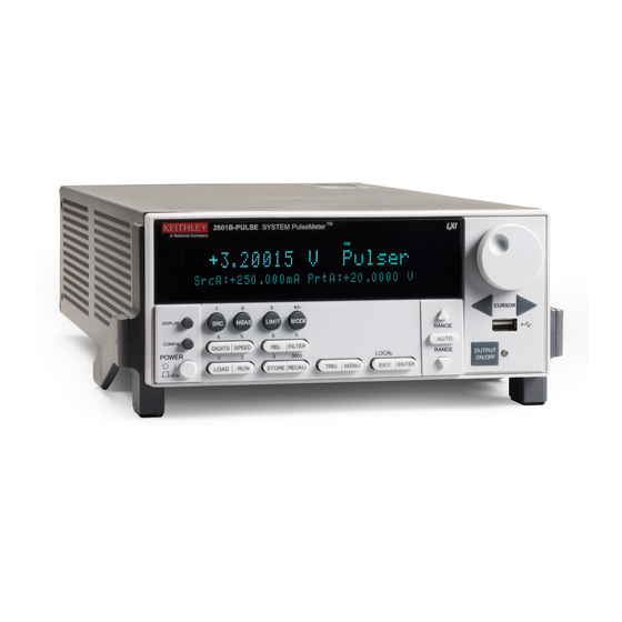
2601B-PULSE System SourceMeter Instrument Safety Supplement Front panel The front panel of the 2601B-PULSE is shown below. The descriptions of the front-panel controls, USB port, and indicators follow the figure. Figure 1: 2601B-PULSE front-panel controls 1. Power switch, display and configuration keys Power switch. - Page 4 2601B-PULSE System SourceMeter Instrument Safety Supplement Performance control Sets the display resolution (4½, 5½, or 6½ digits). DIGITS Sets the measurement speed (FAST, MEDium, NORMAL, HI-ACCURACY, or SPEED OTHER). Speed and accuracy are set by controlling the measurement aperture. Controls relative measurements, which allows a baseline value to be subtracted from a reading.
- Page 5 2601B-PULSE System SourceMeter Instrument Safety Supplement 3. Range keys Selects the next higher source or measure range. Enables or disables source or measure autorange. Selects the next lower source or measure range. In addition to selecting range functions, the up and down range keys change the format for non-range numbers (as an example, when editing the limit value).
-
Page 6: Display Indicators (Not Shown)
2601B-PULSE System SourceMeter Instrument Safety Supplement 8. Display indicators (not shown) The items listed below represent the possible display indicators and their meanings. Indicator Meaning Remote (4-wire) sense selected Source or measure autorange is selected AUTO Instrument is in editing mode EDIT Questionable reading or invalid calibration step Digital filter is enabled... - Page 7 2601B-PULSE System SourceMeter Instrument Safety Supplement 1. FORCE HI and FORCE LO connectors These connectors provide connections for FORCE HI and FORCE LO. 2. SENSE LO and SENSE HI connectors These connectors provide connections for SENSE LO and SENSE HI. 3.
-
Page 8: Power Module
2601B-PULSE System SourceMeter Instrument Safety Supplement 8. LAN RJ-45 connector for a local area network (LAN). The LAN interface supports Auto-MDIX, so either a CAT-5e crossover cable (provided), or a normal CAT-5e straight-through cable (not provided) can be used. 9. USB port This USB-2.0 receptacle (Type B) located on the rear panel is used to connect the instrument to a computer. -
Page 9: Starting Up Your Instrument
2601B-PULSE System SourceMeter Instrument Safety Supplement To prevent damaging heat build-up and ensure specified performance, use the following guidelines. The rear exhaust vent and either the top or both side intake vents must be unobstructed to properly dissipate heat. Even partial blockage could impair proper cooling. Do not position any devices adjacent to the 2601B-PULSE that force air (heated or unheated) toward its cooling vents or surfaces. - Page 10 2601B-PULSE System SourceMeter Instrument Safety Supplement Operating the instrument on an incorrect line voltage may cause damage to the instrument, possibly voiding the warranty. To turn a 2601B-PULSE on and off: 1. Before plugging in the power cord, make sure that the front panel POWER switch is in the off (O) position. 2.
- Page 11 2601B-PULSE System SourceMeter Instrument Safety Supplement Placing a 2601B-PULSE in standby Placing the 2601B-PULSE in standby does not place the instrument in a safe state (an interlock is provided for this function). When the instrument is on, the output may be placed in an active output state (output on) or a standby mode (output off).
-
Page 12: Line Fuse Replacement
2601B-PULSE System SourceMeter Instrument Safety Supplement Line fuse replacement A fuse on the 2601B-PULSE rear panel protects the power line input of the instrument. Follow the below instructions to replace the fuse. You do not need to return your instrument for service if the fuse is damaged. Disconnect the line cord at the rear panel and remove all test leads connected to the instrument before replacing a line fuse. -
Page 13: System Information
2601B-PULSE System SourceMeter Instrument Safety Supplement System information You can display serial number, firmware revision, and calibration dates through the front panel by selecting SYSTEM-INFO from the main menu. To view the system information from the front panel: 1. Press the MENU key. 2. -
Page 14: Display Mode
2601B-PULSE System SourceMeter Instrument Safety Supplement Display mode Use the DISPLAY key to scroll through the various display modes shown in the figure below. Figure 4: Display modes 071374500 April 2020... -
Page 15: Operation Overview
2601B-PULSE System SourceMeter Instrument Safety Supplement Operation overview From the front panel, you can configure the instrument to perform the following source-measure operations: ▪ Source voltage: Measure and display current, voltage, resistance, or power ▪ Source current: Measure and display voltage, current, resistance, or power ▪... -
Page 16: Safety Concerns
2601B-PULSE System SourceMeter Instrument Safety Supplement Safety concerns This instrument can produce high current, high power outputs that can cause heating of connectors and wires. Always use wires and connectors that are rated for the maximum current ratings of the instrument. Failure to provide correctly rated wires and connectors can result in a fire.
Need help?
Do you have a question about the Keithley 2601B-PULSE and is the answer not in the manual?
Questions and answers