Advertisement
Available languages
Available languages
Quick Links
Advertisement

Related Manuals for EAS Electric VRV


Summary of Contents for EAS Electric VRV
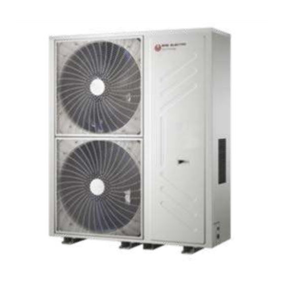
- Page 1 VRVV MANUAL DE INSTALACIÓN Y MANUAL DE USUARIO MODELOS: EVRO-400RDC EVRO-450RDC...
- Page 2 ÍNDICE Manual de instalación ..............3 Manual de usuario ..............20...
- Page 3 Manual de instalación MANUAL DE INSTALACIÓN Pregunte a un distribuidor autorizado o a un instalador profesional calificado para que instale / mantenga el aire ÍNDICE PÁG. acondicionado. La instalación incorrecta puede provocar fugas de agua, descargas eléctricas, fuego, etc. PRECAUCIONES..................3 Apague el interruptor principal de alimentación o el interruptor antes de realizar cualquier trabajo eléctrico.
- Page 4 Manual de instalación Herramientas necesarias para el trabajo de instalación 1) Destornillador 1 2 ) Dobladora de tubo 2) Taladro (65 mm) 1 3 ) Nivel 3) Llaves 1 4 ) Sierra de metal 4) Cortatubos 1 5 ) Puente de manómetros ( Para R410A) 5 ) Detector de fugas de gas 1 6 ) Bomba de vacio ( Para R410A ) 6 ) Cinta métrica...
- Page 5 Manual de instalación 4. INSTALACIÓN DE LA UNIDAD EXTERIOR ADVERTENCIA Pida a un técnico autorizado o a un profesional cualificado que instale y realice el mantenimiento del aire acondicionado. Una mala instalación puede provocar fugas de agua, descargas eléctricas o incendios. No exponga la unidad a la luz del sol directamente ni a otras fuentes de calor.
- Page 6 Manual de instalación 4.4 Dimensiones (Unidad: mm) 4.3 Consumo de la unidad exterior 1) Ventajas de una base fuerte y correcta: 1.La unidad exterior no se caerá. 2.La unidad exterior no generará ruidos provocados por una mala base. 2) Tipos de base 1.Base de soporte de acero 2.Base de hormigón (Vea la Fig.4-6 para la práctica común) Unidad Exterior...
- Page 7 Manual de instalación 5. INSTALACIÓN DE LA TUBERÍA 5.2 Tipos de tubería DE REFRIGERANTE Selección de las tubería Tabla 5-3 5.1 Tuberías de refrigerante Nombre Definición Código 1. Abocardado 1) Use un cortador de tubos para cortar la tubería. (Vea Tubería entra la unidad exterior y el Tubería principal Fig.
- Page 8 Manual de instalación Diámetros de tubería (L2~L5) y distribuidores (B~E) Tabla 5-4 Diámetros de los accesorios de conexión Abocardado (conexión a la válvula de Capacidad de las Tubería (mm) servicio de gas) unidades interiores Distribuidor aguas abajo Líquido EVRI-BP1 A 166 Φ15.9 Φ9.5 EVRI-BP1...
- Page 9 Manual de instalación Las unidades interiores aguas abajo de la tubería L2 son N1, N2 5.5 Ejemplos y su capacidad total es de 80×2=160, el diámetro de la tubería L2 es Φ15.9/Φ9.5, y el distribuidor B debe ser el modelo EVRI- BP1.
- Page 10 Manual de instalación Método de conexión 1 Unidad Exterior Longitud de tubería entre una interior y el distribuidor más cercano Longitud total equivalente máxima El primer distribuidor Lengitud entre la interior más lejana y el primer distribuidor Fig.5-6 Unidades Interiores Método de conexión 2 Unidad Exterior Longitud de tubería entre una interior...
- Page 11 Manual de instalación Abrir: PRECAUCIÓN 1. Inserte una llave Allen en la válvula 2. Cuando la válvula no se pueda girar más, la válvula está abierta. Nitrógeno presurizado (3.9MPa (44kgf/cm ) para R410A] se debe usar en la prueba de estanqueidad. NO haga presión directamente a la válvula de corte.
- Page 12 Manual de instalación 3. Le rogamos usar materiales de aislamiento térmico sin 6.1 Cableado de la unidad exterior holgura para las piezas de conexión de las tuberías de la unidad interior. Corte superior Tubería Cuerpo de la unidad Cinta Comunicación Conexión Comunicación Comunicación...
- Page 13 Manual de instalación 6.2 Esquema eléctrico...
- Page 14 Manual de instalación 6.3 Comprobación de parámetros de la unidad exterior Instrucciones de consulta SW2 Tabla 6-2 Nota Nº. Descripción Normal Frecuencia de funcionamiento 0. – – Dirección de la unidad exterior 1. – – Capacidad de la unidad exterior 8, 10, 12, 14, 16, 18 2.
- Page 15 Manual de instalación 6.4 Placa principal de la unidad exterior Fig.6-3...
- Page 16 Manual de instalación 6.5 Instrucciones de la placa principal de la unidad exterior Tabla 6-3 Nº Descripción Nº Descripción Sensor de temperatura de descarga compresor A Salida de potencia del transformador No.2 Sensor de temperatura de descarga compresor B Puerto de activación del módulo Inverter B Puerto para el módulo Inverter B comprobación de Sensor de temperatura del modulo Inverter voltaje...
- Page 17 Manual de instalación Micro-interruptor S5: Micro-interruptor S8: Micro-interruptor S11: Reservado (por 6–10HP Prioridad calefacción defecto) (por defecto) Ajustes de la unidad exterior Micro-interruptor S10: Prioridad refrigeración 12–18HP Ajustes de la unidad exterior Reservado Prioridad VIP dirección 63 PRECAUCIÓN Solo calefacción Desconectar la alimentación antes de comenzar a realizar cualquier cambio.
- Page 18 Manual de instalación PRECAUCIÓN La conexión incorrecta puede estropear el compresor u otros componentes. El voltaje de comunicación (p, q, e) es débil, nunca lo conecte a un alto voltaje. Los terminales de los cables deben estar bien apretados. El cable de tierra se debe conectarse a tierra. Al conectar a la base del conector, el cable de alimentación estará...
- Page 19 Manual de instalación b. Dispositivo detector de fugas 9. ENTREGA DEL MANUAL AL conectado al sistema de ventilacion USUARIO ud. Interior Los manuales de uso de las unidades interiores y exteriores se deben entregar al usuario. Explique en detalles el contenido del manual de usuario a los clientes.
- Page 20 Manual de usuario MANUAL DE USUARIO ÍNDICE PÁG. Nunca utilice un spray inflamable como un espray para el cabello, cerca de la unidad. Podría causar un incendio. INFORMACIÓN IMPORTANTE DE SEGURIDAD......Nunca toque la salida de aire o las cuchillas horizontales RANGO DE FUNCIONAMIENTO...........
- Page 21 Manual de usuario No instale el equipo de aire acondicionado en un lugar PRECAUCIÓN donde pueda haber gas inflamable. Si el gas se escapa y se mantiene alrededor del equipo, puede provocar una explosión o un incendio. No utilice el aparato de aire acondicionado para otros fines.
- Page 22 Manual de usuario Descripción Observaciones N º. PRECAUCIÓN pantalla Capacidad actual de la Valor real 8. - - unidad interior El dispositivo de protección puede activarse si se enciende la 9. - - 0,1, ……, 9,10 Velocidad del ventilador A ud.
- Page 23 Manual de usuario 2.5 Características del funcionamiento en calefacción El aire caliente no saldrá inmediatamente al principio de encender el equipo aire saldrá de 3 a 5 minutos más tarde (depende de la unidad interior) hasta que el intercambiador de calor de la unidad interior esté...
- Page 24 Manual de usuario 3. MANTENIMIENTO 3.1 Confirmación antes del funcionamiento 3.2 No son averías del A/A 1. Compruebe que el cable a tierra está bien conectado y sin daños. 1. Para las medidas básicas de seguridad, consulte el manual 2. Asegúrese de que se ha instalado un filtro de aire. de uso de la unidad interior.
- Page 25 Manual de usuario Pantalla Código Observaciones Mal funcionamiento o protección X representa el sistema, 1 es sistema A, 2 es sistema B Protección de alto voltaje DC X representa el sistema, 1 es sistema A, 2 es sistema B Reservado 4²...
- Page 26 Si el equipo presenta un funcionamiento anormal, por favor, en primer lugar desconecte la fuente de alimentación, y póngase en contacto con nuestro servicio la postventa (SAT). Para consular su servicio técnico más cercano, acceda a la página web: www.easelectric.es...
- Page 27 VRVV INSTALLATION'S AND OWNER'S MANUAL MODELS: EVRO-400RDC EVRO-450RDC...
- Page 28 Table of contents Installation's manual ..............3 Owner's manual ..............23 ErP Information ............... 30...
-
Page 29: Table Of Contents
CONTENTS PAGE WARNING PRECAUTIONS..................3 Ask an authorized dealer or qualified installation professional to ATTACHED FITTINGS................4 install/maintain the air conditioner. CONSTRUCTION INSPECTION..............4 Inappropriate installation may result in water leakage,electric shock or fire. OUTDOOR UNIT INSTALLATION..............5 Turn off the main power supply switch or breaker before INSTALL THE CONNECTING PIPE............7 attempting any electrical work. -
Page 30: Attached Fittings
6) Reamer 16) Metal saw 7) Gas leak detector 17) Gauge manifold (Charge hose:R410A special requirement) 8) Tape measure 18) Vacuum pump (Charge hose:R410A special requirement) 9) Thermometer 19) Torque wrench 10) Mega-tester 1/4(17mm)16N•m (1.6kgf•m) 11) Electro circuit tester 3/8(22mm)42N•m (4.2kgf•m) 12) Hexagonal wrench 1/2(26mm)55N•m (5.5kgf•m) 13) Flare tool... -
Page 31: Outdoor Unit Installation
4. OUTDOOR UNIT INSTALLATION WARNING Ask an authorized dealer or qualified installation professional to install maintain the air conditioner.Inappropriate installation may result in water leakage,electric shock or fire. Do not expose the unit directly to sunlight and other souces of heat. Add a cover if necessary to prevent the unit from direct sunlight. - Page 32 4.4 Dimension(Unit: mm) 4.3 Outdoor unit basement 1)Advantages of a strong and correct basement : ①Outdoor unit won’t subside ②Outdoor unit won’t generate abnormal noise caused by improper basement. 2)Basement types ①Steel-frame basement ②Concrete basement(See Fig.4-6 for common practice) Outdoor unit Φ10 expansion bolt Rubber anti-vibration Concrete...
-
Page 33: Install The Connecting Pipe
5.2 Pipe types 5. INSTALL THE CONNECTING PIPE Refrigerant settings 5.1 Refrigerant pipes Table 5-3 1.Flare 1)Cut the pipe with a knife.(See Fig.5-1) Names Piping position Code 2)Fit the pipe to the flare of connecting nut(Table 5-1) Pipe between the outdoor unit and Main pipe indoor-side first manifold Burr... - Page 34 Dimensions of connecting pipe diameters in accessory Reference table of R410A indoor unit connecting pipe Table 5-4 Flare(connecting to gas side stop valve) Main pipe dimensions Downstream indoor Applicable unit capacity manifolds Gas pipe Liquid pipe A<166 Φ15.9 Φ9.5 EVRI-BP1 166≤A<230 Φ19.1 Φ9.5...
- Page 35 5.5 Examples The downstream inner units of the main pipe L2 are N1, N2, and its total capacity is 80×2=160, the size of pipe L2 isΦ15.9/Φ9.5, and the branch pipe B should be EVRI-BP1. The downstream inner units of the main pipe L4 are N3, N4, and Outdoor unit its total capacity is 71×2=142, the size of pipe L4 isΦ15.9/Φ9.5, and the branch pipe D should be EVRI-BP1.
- Page 36 The first connecting methond Outdoor unit Pipe length(From the nearest branch pipe equivalent length) Maximum pipe equivalent length The first manifold (From the first line branch pipe) Maximum pipe equivalent length Indoor Unit Fig.5-6 The second connecting methond Outdoor unit Pipe length(From the nearest manifold equivalent length) Indoor unit farthest pipe equivalent...
- Page 37 Open approach: CAUTION 1. Insert a hexagonal wrench into the valve rod and spin anticlockwise. 2. When the valve rod can’t be spinned any more, the valve is Pressured nitrogen (3.9MPa (44kgf/cm ) for R410A] should open. be used in the airtight test. DO NOT pressure to the stop valve directly.(See Fig.5-8) Close approach: The airtight test should never use any oxygen,flammable gas...
-
Page 38: Electrical Wiring
6.1 Outdoor unit wiring terminal instructions 3. Please use attached heat-insulating materials do the heat insulation without clearance for the connecting parts of the indoor unit pipes. Cut from upward X Y E P Q E K1 K2 E O A E Site pipe side The unit body Affiliated heat pump belt... - Page 39 6.3 Outdoor unit main control board Fig.6-3...
- Page 40 6.4 Outdoor main control board instructions Table 6-3 Contents Contents Discharge temp. sensed port of the inverter Power output of the No.2 transformer compressor A Discharge temp. sensed port of the inverter Activation port of inverter module B compressor A or B Port for inverter module B voltage inspection Ttemp.
- Page 41 S3 definition: S8 definition olny for 33.5kW/40kW: Night Silent mode Reserve (Default the Factory Set) S8 definition olny for 45kW: Silent mode Default the Factory Set Reserve S10 function definition: None Silent mode Reserve S4 definition: S11 function definition: Static pressure mode is 0 MPa(Default the 6-10HP Factory Set)
- Page 42 Outdoor power supply 6.6 Electric control system wiring diagram Switch Fuse Outdoor unit Outdoor unit monitor power supply K2 E O Y E P B C N Outdoor unit monitor (Optional) K1K2 E Power supply of indoor unit centralized controller Indoor unit centralized controller (Optional)
- Page 43 8. TEST RUNNING CAUTION 8.1 Check points before test running Signal wire is 3-core, polarized wire. Use 3-core shield wire to 1. If indoor and outdoor units have been installed properly. prevent interference. The grounding method now is grounding the 2.
- Page 44 9.1 Important information for the used refrigerant This product has the fluorinated gas, it is forbidden to release to air. Refrigerant type: R410A; Volume of GWP: 2088; GWP=Global Warming Potential Factory charge Model Refrigerant/kg tonnes CO equivalent 9.00 18.79 40kW 12.00 25.06 45kW...
- Page 45 8.2 Information requirements for air-to-air conditioners Cooling mode: Information requirements for air-to-air conditioners Model(s):EVRO-400RDC Test matching indoor units from2,non-duct:4×MI-71Q4* + 2×MI-45Q4* Outdoor side heat exchanger of air conditioner:air Indoor side heat exchanger of air conditioner:air Type:compressor driven If applicable:driver of compressor:electric motor Item Symbol Value...
- Page 46 Heating mode: Information requirements for air-to-air conditioners Model(s):EVRO-400RDC Test matching indoor units from2,non-duct:4×MI-71Q4* + 2×MI-45Q4* Outdoor side heat exchanger of air conditioner:air Indoor side heat exchanger of air conditioner:air Idication if the heater is equipped with a supplementary heater:no If applicable:driver of compressor:electric motor Parameters shall be declared for the anerage heating season,parameters for the warmer and colder heating seasoms are optional Item Symbol...
- Page 47 Cooling mode: Information requirements for air-to-air conditioners Model(s):EVRO-450RDC Test matching indoor units from2,non-duct:6×MI-71Q4* Outdoor side heat exchanger of air conditioner:air Indoor side heat exchanger of air conditioner:air Type:compressor driven If applicable:driver of compressor:electric motor Item Symbol Value Unit Item Symbol Value Unit Rated cooling...
- Page 48 Heating mode: Information requirements for air-to-air conditioners Model(s):EVRO-450RDC Test matching indoor units from2,non-duct:6×MI-71Q4* Outdoor side heat exchanger of air conditioner:air Indoor side heat exchanger of air conditioner:air Idication if the heater is equipped with a supplementary heater:no If applicable:driver of compressor:electric motor Parameters shall be declared for the anerage heating season,parameters for the warmer and colder heating seasoms are optional Item Symbol...
- Page 49 This air conditioner comprises an indoor unit, outdoor unit, and a connection pipe. Indoor unit Outdoor unit Air outlet Air inlet Fig .1 Fixing support Refrigerant pipe connector Connection pipe NOTE All the pictures in this manual are for explanation purpose only. They may be slightly different from the air conditioner you purchased(depend on model).
- Page 50 Never touch the air outlet or the horizontal blades while the swing flap is in operation. CONTENTS PAGE Fingers may become caught or the unit may break down. Never put any objects into the air inlet or outlet. Objects touching the fan at high speed can be dangerous. Never inspect or service the unit by yourself.
- Page 51 Do not place items which might be damaged by moisture Poor environmental conditions, the appliance should be under the indoor unit. maintained a month and a half or so; If the environment con- Condensation may form if the humidity is above 80%, the dition is good, may be extended appropriately maintenance drain outlet is blocked or the filter is polluted.
- Page 52 2.2 Constraint Cooling Table of force cooling frequency Table 2-2 1.Constraint Cooling Mode Force cooling rate(Hz) Outdoor unit main control board has constraint cooling key: SW1 (see Fig.2-1). One press will send constraint cooling signal to all the indoor unit. Constrain all the indoor unit to constraint cooling 33.5kW/40kW operation.
- Page 53 The display contents as followings: 2.9 Mishandling in operation Normal display:When standby, the high position displays the address of the outdoor nuit,and the low position displays the Qty.of indoor units that can communi If mishandling happens because of lighting or mobile wireless, -cate with outdoor unit .When it is operating, it will display the rotation frequency of please shut off the manual power switch, and turn on again, the compressor.
- Page 54 4. MAINTENANCE 4.1 Confirmation before operating 4.2 NON-A/C errors 1. Make sure if the ground wire is broken or fall off. 1. For common protections, please refer to indoor unit operation 2. Make sure if a air strainer has been installed. manual.
- Page 55 CAUTION Please do not change the power supply by yourself incase of danger; and do not fix the air-conditioner by yourself. 4.4 Cleaning WARNING Stop the unit and cut off the power before cleaning for safety’s sake. Pay attention to T1 thermal bulb when cleaning. DO NOT drop T1 thermal bulb cable,or dismantle it before cleaning and reinstall after cleaning.
- Page 56 ErP Information Fan Types Axial fan Directive (or Standard) for Regulation ErP Directive 2009/125/EC COMMISSION REGULATION (EU) No 327/2011 Model Name WZDK170-38G-1+ZL-560*169*15*4(ZJ)850 Rev. Prepare by Specified Information of Fan: Information Item Comment η 29.7% target Overall efficiency (η 32.2% Pass or not (Criteria: η ≥η...
- Page 57 ErP Information Fan Types Axial fan Directive (or Standard) for Regulation ErP Directive 2009/125/EC COMMISSION REGULATION (EU) No 327/2011 Model Name WZDK170-38G-1+ZL-560*169*15*4(ZJ)850 Rev. Prepare by Specified Information of Fan: Information Item Comment η 29.6% target Overall efficiency (η 34.6% Pass or not (Criteria: η ≥η...
- Page 58 ErP Information Fan Types Axial fan Directive (or Standard) for Regulation ErP Directive 2009/125/EC COMMISSION REGULATION (EU) No 327/2011 Model Name WZDK170-38G-1+ZL-560*169*15*4(ZJ)900 Rev. Prepare by Specified Information of Fan: Information Item Comment η 30.3% target Overall efficiency (η 32.9% Pass or not (Criteria: η ≥η...
- Page 59 ErP Information Fan Types Axial fan Directive (or Standard) for Regulation ErP Directive 2009/125/EC COMMISSION REGULATION (EU) No 327/2011 Model Name WZDK170-38G-1+ZL-560*169*15*4(ZJ)900 Rev. Prepare by Specified Information of Fan: Information Item Comment η 30.0% target Overall efficiency (η 33.4% Pass or not (Criteria: η ≥η...
- Page 60 ErP Information Fan Types Axial fan Directive (or Standard) for Regulation ErP Directive 2009/125/EC COMMISSION REGULATION (EU) No 327/2011 Model Name WZDK170-38G-1+ZL-560*169*15*4R(YS)850 Rev. Prepare by Specified Information of Fan: Information Item Comment η 29.6% target Overall efficiency (η 33.9% Pass or not (Criteria: η ≥η...
- Page 61 ErP Information Fan Types Axial fan Directive (or Standard) for Regulation ErP Directive 2009/125/EC COMMISSION REGULATION (EU) No 327/2011 Model Name WZDK170-38G-1+ZL-560*169*15*4R(YS)850 Rev. Prepare by Specified Information of Fan: Information Item Comment η 29.6% target Overall efficiency (η 34.9% Pass or not (Criteria: η ≥η...
- Page 62 ErP Information Fan Types Axial fan Directive (or Standard) for Regulation ErP Directive 2009/125/EC COMMISSION REGULATION (EU) No 327/2011 Model Name WZDK560-38G(B)+ZL-700*202*20-3N Rev. Prepare by Specified Information of Fan: Information Item Comment η 31.0% target Overall efficiency (η 36.8% Pass or not (Criteria: η ≥η...
- Page 63 ErP Information Fan Types Axial fan Directive (or Standard) for Regulation ErP Directive 2009/125/EC COMMISSION REGULATION (EU) No 327/2011 Model Name WZDK560-38G(B)+ZL-700*200*20-4N Rev. Prepare by Specified Information of Fan: Information Item Comment η 30.9% target Overall efficiency (η 35.7% Pass or not (Criteria: η ≥η...
- Page 64 www.easelectric.es...
Need help?
Do you have a question about the VRV and is the answer not in the manual?
Questions and answers