
Related Manuals for EAS Electric VRV EVR 6 Series


Summary of Contents for EAS Electric VRV EVR 6 Series
- Page 1 SISTEMA VRV SERIE EVR6 VRV SYSTEM EVR SERIES EVRO120V EVRO140V EVRO160V MANUAL DE INSTRUCCIONES INSTRUCTION MANUAL...
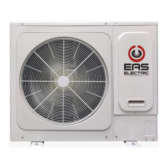
- Page 2 Unidad exterior Entrada aire Salida de aire Conexión tuberías Patas refrigerante Fig.1 NOTA Todas las imágenes de este manual tienen sólo fines explicativos. Pueden ser ligeramente distintos del aparato que usted ha comprado, según el modelo. Prevalece el aspecto real del aparato. 16kW conforme con IEC 61000-3-12.
-
Page 3: Table Of Contents
CONTENIDO PÁGINA Nunca sustituya un fusible por otro con un voltaje nominal incorrecto o con distintos cables si se funde un fusible. INFORMACIÓN IMPORTANTE DE SEGURIDAD.......1 El uso de cables de cobre puede causar una avería de la PIEZAS....................2 unidad o un incendio. RANGO DE FUNCIONAMIENTO..........3 No debe exponer su cuerpo al flujo de aire durante un FUNCIONAMIENTO Y RENDIMIENTO..........3... - Page 4 No maneje el aparato con las manos mojadas. Puede Este aparato está diseñado para ser utilizado por usuarios expertos o capacitados en tiendas, en la provocar una descarga eléctrica. industria ligera y en granjas, o para uso comercial por No toque las aletas del intercambiador de calor. Estas personas no profesionales.
-
Page 5: Rango De Funcionamiento
4. FUNCIONAMIENTO Y RENDIMIENTO Contenido mostrado Monitor "--" ↓ 4.1 Sistema de protección Frecuencia actual Último código de error ↓ Modo de funcionamiento Este sistema de protección permite al aire acondicionado ↓ Nº versión programa detenerse cuando detecta un funcionamiento anormal. Velocidad funcionamiento ventilador Modo prioridad... -
Page 6: Códigos De Error De La Unidad Exterior
4.5 Refrigeración y calefacción Durante el funcionamiento, el motor ventilador de la unidad exterior puede dejar de funcionar por alta • Las unidades interiores de aire acondicionado centralizado inteligente temperatura. inverter pueden controlarse independientemente, pero las unidades interiores de un mismo sistema no pueden funcionar en refrigeración Durante el funcionamiento del ventilador, si las otras y calefacción al mismo tiempo. - Page 7 Tabla 5-2 (10/12KW) Nº Tipo de error o protección Recuperación Código Recuperable Error comunicación entre placa control y bornero de comunicación Error comunicación unidad interior Recuperable Error sonda temperatura T3 o T4 Recuperable Protección voltaje de entrada Recuperable Protección ventilador DC Recuperable Irrecuperable Error EEPROM...
- Page 8 Temperatura ambiente menor o igual a -5ºC en refrigeración (error en u. exterior) Recuperable Si el problema persiste, póngase en contacto con su distribuidor o con el servicio técnico oficial de EAS Electric Smart Technology, y proporcióneles el modelo del producto y los detalles sobre el fallo.
-
Page 9: Solución De Problemas
LOS SIGUIENTES SÍNTOMAS NO Síntoma 4.2: Unidad interior, unidad exterior SON FALLOS DEL APARATO Se puede oír un sonido sibilante continuo cuando el sistema está en funcionamiento. Es el sonido del gas refrigerante Síntoma 1: El sistema no funciona: fluyendo por las unidades interiores y exteriores. El aire no empieza a funcionar inmediatamente tras pulsar sonido sibilante... - Page 10 Tabla 7-1 Síntomas Causas Solución Fallo de corriente. Espere a que vuelva la Interruptor de corriente desconectado. corriente. Conecte la corriente. El fusible del interruptor puede haberse Sustituya el fusible. La unidad no se enciende quemado. Las pilas del mando se han Sustituya las pilas o compruebe agotado o hay algún otro problema en el mando.
- Page 11 7.2 Problemas del mando y causas Antes de solicitar la asistencia del servicio técnico, consulte estos puntos. (véase Tabla 7-2) Tabla 7-2 Síntomas Causas Solución Cuando selecciona modo Compruebe si el MODO automático, aire acondicionado indicado en el display es cambia la velocidad del ventilador "AUTO".
- Page 12 INSTRUCCIONES DE INSTALACIÓN CONTENIDO PÁGINAS ADVERTENCIA PRECAUCIONES................10 ACCESORIOS .................11 Si el cable de alimentación está dañado, debe sustituirlo el fabricante, su servicio técnico o un técnico igualmente INSTALACIÓN UNIDAD EXTERIOR ..........12 cualificado para evitar riesgos. INSTALACIÓN TUBERÍA CONEXIÓN ...........13 Se debe conectar al cableado fijo un interruptor de desconexión multipolar con una separación de al menos 3mm en todos los CABLEADO ELÉCTRICO.
- Page 13 Compruebe si falta algún accesorio de la lista anterior. Debe 1/4(17mm)16N•m (1.6kgf•m) conservar todos los accesorios. 3/8(22mm)42N•m(4.2kgf•m) Todos los accesorios deben ser de EAS Electric. 1/2(26mm)55N•m(5.5kgf•m) Mando por cable/a distancia — se vende por separado. Sellante 5/8(5/8mm)120N•m (12.0kgf•m) de salida — se vende por separado.
- Page 14 ATENCIÓN Instale la unidad en un lugar que pueda ofrecer suficiente • Instale la unidad interior de forma que no se bloquee la salida de aire. espacio para la instalación y el mantenimiento. No la instale • Cuando se instala la unidad exterior en un lugar que siempre está en lugares que tengan requisitos especiales de ruido, como el expuesto a vientos fuertes como en la costa o en un edificio muy alto, dormitorio.
- Page 15 Instalación de una sola unidad (Pared u obstáculo) Entrada de aire > 300 Espacio de > 300 mantenimiento cable y tubería Superficie entrada de aire Fig.3-4 > 600 14/16kW > 2000 Salida de aire Fig.3-4 Conexión en paralelo de dos o más unidades >...
- Page 16 ATENCIÓN NOTA Salida de tubería lateral: retire la chapa en forma de L para poder Todas imágenes este manual solo para instalar el cableado. fines explicativos. Pueden ser ligeramente diferentes de su Salida trasera: Retire la placa de goma junto a la tapa de la tubería aparato (según el modelo).
- Page 17 Líquido NOTA Abocardado Abocardado 10kW Soldadura o abocardado Abocardado Utilice sólo los distribuidores especiales proporcionados por EAS Electric Smart Technology. No hacerlo puede conllevar Soldadura o abocardado 12kW Abocardado averías. Soldadura o abocardado 14kW Abocardado Si la distancia entre la primera derivación y la última unidad interior es superior a 15m, utilice el segundo método.
- Page 18 Diámetro tubería del conector en la unidad exterior 4.6 Ilustración Tabla 4-7 Tubería Diámetro tubería conector unidad exterior Unidad exterior (ejemplo: 160) Modelo Líquido (kW) (28) Unidades interior (28) (28) Primera derivación (28) (28) (22) Fig.4-6 ATENCIÓN: En el supuesto mostrado, la longitud total equivalente Tabla 4-8 de las tuberías de gas y líquido es de más de 90m.
- Page 19 Diferencia de longitud y altitud permitida de la tubería de refrigerante tabla 4-11 Valor permitido Tuberías ≤50m(8kW) Longitud total real de la tubería ≤65m(10/12kW) L1+L2+L3+L4+L5 +a+b+c+d+e+f ≤100m(14/16kW ≤35m(8kW) Longitud real L1+L2+L3+L4+L5+f(Primer método de conexión) ≤45m(10/12kW) ≤60m(14/16kW) Longitud máxima (L) or L1+L3+L5+f(Segundo método de conexión) ≤40m(8kW) Longitud equivalente ≤50m(10/12kW)
- Page 20 Segundo método de conexión Unidad exterior Longitud equivalente tubería del distribuidor más cercano Longitud equivalente máxima (desde la primera derivación) Longitud equivalente máxima Primera derivación Unidad interior Fig.4-8 4.7 Limpieza de las tuberías (Si la presión no puede reducirse a menos de -100,7 kPa después de dos horas de aspiración, repita el proceso de ruptura de vacío y Asegúrese de que no haya suciedad ni agua antes de vaciado).
- Page 21 5. CABLEADO ELÉCTRICO Alimentación ud. exterior Interruptor Fusible Alimentación del control centralizado Mando centralizado U. exterior (opcional) P Q E X Y E Use cable apantallado y conecte a tierra la malla blindada. U. interior U. interior U. interior U. interior Fusible Fusible Fusible...
- Page 22 En la unidad solo se puede utilizar el medidor dedicado de EAS Electric. Para conocer el método de cableado del medidor, consulte al servicio técnico de EAS Electric Smart Technology. Los modelos de 8kW no tienen interfaz de multímetro digital; y la interfaz de multímetro digital está...
- Page 23 5.2.3 Método de fijación de cables de alimentación y señal ATENCIÓN 1. Fijación del cable de alimentación: • Cuando el cable de alimentación esté paralelo al cable de señal, 10/12kw 14/16kw compruebe que estén encerrados en los conductos respectivos y que tengan una separación razonable.
- Page 24 COMPROBACIÓN DE FUNCIONAMIENTO NOTA Siga las instrucciones de la tapa de la caja de conexiones eléctricas. El diámetro del alambre y la longitud continua están bajo la condición de que la vibración de voltaje esté dentro del 2%. Si la longitud continua muestra valores excesivos, elija ATENCIÓN el diámetro del cable siguiendo las regulaciones pertinentes.
- Page 25 NOTA DISPOSICIÓN DE ELIMINACIÓN Presione el botón "Restricción de enfriamiento" para llevar a cabo el proceso de reciclaje de refrigerante. Mantenga la presión baja por encima de 0,2 MPa; de lo contrario, el compresor puede Con base en la directiva europea 2012/19 / UE quemarse.
- Page 26 CONDICIONES DE LA GARANTÍA COMERCIAL Este producto tiene una garantía de reparación de dos años a partir de la fecha de venta, contra todo defecto de funcionamiento proveniente de la fabricación, incluyendo mano de obra y piezas de recambio, y cinco años de garantía en el compresor (solo componente).
- Page 27 Daños en fusibles, lamas, focos, flujostato de caudal, filtros y otros elementos derivados del desgaste normal debido a la operación del equipo. Las averías que tengan su origen o sean consecuencia directa o indirecta de: contacto con líquidos, productos químicos y otras sustancias, así como de condiciones derivadas clima...
- Page 28 English Air inlet Air outlet Mounting Refrigerant pipe bracket connector Fig.1 NOTE All the pictures in this manual are for explanation purpose only. They may be slightly different from the air conditioner you purchased(depend on model). The actual shape shall prevail. 16kW complying with IEC 61000-3-12.
- Page 29 CONTENTS PAGE The remote controller may be damaged. IMPORTANT SAFETY INFORMATION..........1 Never replace a fuse with that of wrong rated current or PARTS NAMES................2 other wires when a fuse blows out. OPERATION RANGE..............3 Use of wire or copper wire may cause the unit to break down or cause a fire.
-
Page 30: Parts Names
In order to avoid injury, do not remove the fan guard of This appliance is intended to be used by expert or trained the outdoor unit. users in shops, in light industry and on farms, or for commercial use by lay persons. Do not operate the air conditioner with a wet hand. -
Page 31: Operation Range
4. OPERATION AND PERFORMANCE Displayed contents Display "--" ↓ Current frequency Last error or protection code 4.1 Protection Equipment ↓ Operating mode Program version NO. ↓ This Protection Equipment will enable the Air Conditioner to stop Operating fan speed and leave Priority mode when the Air Conditio ner is to be directed running compulsively. -
Page 32: Malfunction Code Of Outdoor Unit
4.5 Cooling and heating operation During operation, the fan motor in the outdoor unit may stop running under high temperature. The indoor unit of the intelligent inverter centralized air conditioner can be controlled solely, but the indoor unit in the During Fan Operation, if other Indoor Units are running on same system can not run cooling and heating at the same time. - Page 33 Table 5-2 (10/12KW) Fault or protection type Recovery mode Error code Recoverable Communication fault between main control board and communication terminals block IDU communication error Recoverable T3 or T4 temperature sensor error Recoverable Input voltage protection Recoverable DC fan protection Recoverable Unrecoverable EEPROM error...
- Page 34 Ambient temperature less than or equal to -5 ℃ in cooling mode (ODU reports the fault) Recoverable If the problem remains, please contact the distributor or EAS Electric Smart Technology's air conditioner customer service center, and provide info about the product model and the fault details.
-
Page 35: Following Symptoms Are Not Air Conditioner Troubles
6. FOLLOWING SYMPTOMS ARE NOT AIR Symptom 4.2: Indoor unit, outdoor unit CONDITIONER TROUBLES A continuous low hissing sound is heard when the system is in operation. Symptom 1: The system does not operate This is the sound of refrigerant gas flowing through both indoor and outdoor units. - Page 36 Table 7-1 Symptoms Causes Solution Power failure. Wait for the comeback of power. Power switch is off. Switch on the power. Fuse of power switch may have burned. ReplLocation: Unit does not start Unit does not start Batteries of remote controller exhausted Replace the batterises or check the or other problem of controller.
- Page 37 7.2 Troubles and causes of remote controller Before asking for serving or repairing, check the following points. (see in Table 7-2) Table 7-2 Symptoms Causes Solution Check whether the MODE When the automatic mode is indicated on the display is selected, the air conditioner will "AUTO"...
- Page 38 WARNING INSTALLATION GUIDELINES If the supply cord is damaged, it must be replaced by the CONTENTS PAGE manufacturer or its service agent or a similarly qualified person in order to avoid a hazard. An all-pole disconnection switch having a contact separation of PRECAUTIONS..................1 at least 3mm in all poles should be connected in fixed wiring.
-
Page 39: Attached Fittings
Check if any accessory in the above figure is missing. All the 21) Vacuum pump adapter accessories must be kept properly. All the fittings should be EAS Electric Smart Technology fittings Wired/Remote controller — purchase separately Outlet sealant — purchase separately. -
Page 40: Outdoor Unit Installation
Near a private power station or high Frequency equipment. CAUTION Install indoor unit, outdoor unit, power cord and connecting wire at least 1m away from TV set or radio to prevent noise or Install the outdoor unit at a place where discharge air is not blocked. picture interference. - Page 41 Single unit installation (Wall or obstacle) Air inlet surface > 300 > 300 Maintenance cable and pipeline surface Air inlet surface Fig.3-4 > 600 14/16kW > 2000 Air outlet surface Fig.3-4 Parallel connect the two units or above > 300 >...
-
Page 42: Install The Connecting Pipe
CAUTION NOTE Side out pipe: please remove the L-shape metal plate, otherwise All the pictures in this manual are for explanation purpose only. can not wiring. They may be slightly different from the air conditioner you Back out pipe:please wipe off the piping support rubber blanket purchased(depend on model).The actual shape shall prevail. - Page 43 4.4 Connecting method R410A Indoor unit connecting pipes diameters Table 4-3 Select refrigerant pipe Main pipe size(mm) Total capactiy of Branch Pipe the downstream Table 4-2 Iiquid pipe Air pipe inner units Pipe definition Pipe connect position Code EVRI-BP1 A<160 Φ15.9 Φ9.5 The pipe between outdoor unit to the...
- Page 44 Pipe diameter of the connector in the outdoor unit's body 4.6 Illustration Table 4-7 Piping Pipe diameter of outdoor unit's connector(mm) Outdoor Unit(Take Model 160 for example) side MODEL Gas Side Liquid Side (kW) Φ15.9 Φ9.5 (28) Intdoor Units Φ15.9 Φ9.5 (28) (28)
- Page 45 Allowable length and altitude difference of refrigerant pipe table 4-11 Pimitted value Piping ≤50m(8kW) +a+b+c+d+e+f Total Pipe Length(Actual) ≤65m(10/12kW) L1+L2+L3+L4+L5 ≤100m(14/16kW) ≤35m(8kW) Actual Length L1+L2+L3+L4+L5+f(The first connect methond) ≤45m(10/12kW) ≤60m(14/16kW) Maximum Piping(L) or L1+L3+L5+f(The second connect methond) ≤40m(8kW) Equivalent Length ≤50m(10/12kW) ≤70m(14/16kW) L2+L3+L4+L5+f(The first connect methond)
- Page 46 The second connect method Pipe length(From the nearest branch Outdoor unit pipe equivalent length Maximum pipe equivalent length (From the first line branch pipe) Maximum pipe equivalent length The First Line Branch Pipe Indoor unit Fig.4-8 4.7 Remove Dirt or Water in the Piping (If the pressure cannot be decreased to lower than -100.7 kPa after two-hour vacuumizing, repeat the vacuum breaking and vacuum Make sure there is no any dirt or water before connecting...
-
Page 47: Electrical Wiring
5. ELECTRICAL WIRING Outdoor power supply On/Off switch Fuse Power supply of centralized controller Centralized controller (optional) P Q E X Y E Please use the shielded wire, and the shield layer must be grounded. Fuse Fuse Fuse Fuse On/Off switch Indoors Power supply Distribution box... - Page 48 ODU power supply 220V~240V 50Hz Fig. 5-2 Only the dedicated meter of EAS Electric Smart Technology can be used on the unit. For the wiring method of the meter, please consult ÿ ÿ E AS Electric Smart Technology’s professional service personnel.
- Page 49 5.2.3 The method of fixing the power cord and signal line: CAUTION 1.The method of fixing the power cord : When the power cable is parallel to the signal wire, make sure 10/12kw 14/16kw that they are enclosed in respective conduits and are kept a reasonable wire spacing.
-
Page 50: Test Running
6. TEST RUNNING NOTE Operate according to "gist for test running" on the electric control box cover. The wire diameter and continuous length is under the condition that the voltage vibration is within 2%. If the continuous length is exceed showing value, choose the wire diameter follow relevant regulation. -
Page 51: Turn Over To Customer
NOTE DISPOSAL OF APPLIANCES Please press “constraint cool” button to carry out refrigerant recycling process. Keep the low pressure above 0.2MPa, other wise compressor may be burnt out. european directive 2012/19 wasted electrical electronic equipments (WEEE), requires that household electrical 7.1 Important information for the used appliances must not be disposed of in the normal refrigerant... - Page 52 COMMERCIAL GUARANTEE CONDITIONS FOR AIR CONDITIONING This product has a two-year repair guarantee from the date of sale, against all manufacturing malfunctions, including repairwork and replacement parts, and a five-year guarantee on the compressor (component only). To justify the purchase date, it will be mandatory to present the end user's invoice or purchase receipt and the installation company data.
- Page 53 15. Damage to fuses, blades, lamps, flow switch, filters and other elements derived from normal wear and tear due to the operation of the equipment. 16. Faults that have their origin or are a direct or indirect consequence of: contact with liquids, chemicals and other substances, as well as conditions derived from the climate or the environment: earthquakes, fires, floods, excessive heat or any other external force , such as insects, rodents and other animals that may have access to...
Need help?
Do you have a question about the VRV EVR 6 Series and is the answer not in the manual?
Questions and answers