Table of Contents
Advertisement
Available languages
Available languages
Quick Links
AIRE ACONDICIONADO TIPO CASETE / CASSETE-TYPE AIR CONDITIONER
MANUAL DE USUARIO
Casete baja silueta
OWNER'S MANUAL
Super-Slim Cassette
NOTA IMPORTANTE
Lea atentamente este manual antes de instalar o poner en funcionamiento su
unidad de aire acondicionado y consérvelo para futuras referencias.
IMPORTANT NOTE:
Read this manual carefully before installing or operating your new air conditioning
unit. Make sure to save this manual for future reference.
V.1
Advertisement
Chapters
Table of Contents

Subscribe to Our Youtube Channel
Related Manuals for EAS Electric Super-Slim Cassette Series


Summary of Contents for EAS Electric Super-Slim Cassette Series
- Page 1 AIRE ACONDICIONADO TIPO CASETE / CASSETE-TYPE AIR CONDITIONER MANUAL DE USUARIO Casete baja silueta OWNER’S MANUAL Super-Slim Cassette NOTA IMPORTANTE Lea atentamente este manual antes de instalar o poner en funcionamiento su unidad de aire acondicionado y consérvelo para futuras referencias. IMPORTANT NOTE: Read this manual carefully before installing or operating your new air conditioning unit.
- Page 2 ESPAÑOL Tabla de contenido Manual de usuario Precauciones de seguridad ............ 04 LA SEGURIDAD ES LO PRIMERO Piezas de la unidad interior y funciones principales ........... Funcionamiento manual ...........
-
Page 3: Table Of Contents
Cuidado y mantenimiento ......09 Unidad de mantenimiento ......09 Cómo limpiar el filtro de aire ......Reparación de fugas de refrigerante ..Preparación para períodos de no uso ..Solución de problemas ......... Problemas comunes ......11 Consejos para solucionar problemas Directrices europeas relativas a la eliminación .......... - Page 4 Precauciones de seguridad Gracias por adquirir este aparato de aire acondicionado que. Este manual le proporcionará la información sobre la forma de operar, mantener y solucionar problemas de su acondicionador de aire. Siguiendo las instrucciones que se asegurará el buen funcionamiento y prolongar la vida útil de la unidad.
- Page 5 PRECAUCIÓN Este aparato puede ser utilizado por niños de 8 • años y mayores y personas con discapacidad NO TOQUE la salida de aire, mientras que la física, sensorial o mental o falta de experiencia • y conocimiento, si se le ha dado la supervisión solapa abatible está...
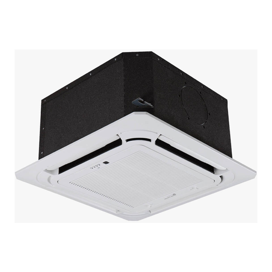
- Page 6 Piezas de la unidad interior y funciones principales Partes de la unidad Panel de visualización Salida de aire Lama Entrada de aire Fig. 2.1 Condiciones de funcionamiento Utilizar el sistema bajo las siguientes temperaturas para un funcionamiento seguro y eficaz. Si se utiliza el acondicionador de aire en diferentes condiciones, puede funcionar mal o ser menos eficiente.
- Page 7 Características Configuración predeterminada Rejilla Ángulo función de memoria (opcional) Cuando se reinicia el acondicionador de aire Algunos modelos están diseñados con una función después de un fallo de alimentación, se pondrá de memoria ángulo de las aletas. Cuando la unidad por defecto a los ajustes de fábrica (modo se reinicia después de un fallo de alimentación, el AUTO, ventilador AUTO, 24 °...
- Page 8 Funcionamiento manual Este panel de visualización de la unidad interior se puede utilizar para hacer funcionar la unidad en caso de que el control remoto se ha perdido o está fuera de baterías. Botón manual Indicador de funcionamiento Indicador de alarma Pantalla LED Receptor de infrarrojos Indicador del temporizador...
-
Page 9: Cuidado Y Mantenimiento
Cuidado y mantenimiento ADVERTENCIA:NO ELIMINAR O Precauciones de seguridad LIMPIAR EL FILTRO USTED MISMO Póngase en contacto con un técnico de servicio • autorizado para su reparación o mantenimiento. Quitar y limpiar el filtro puede ser peligroso. El la reparación y el mantenimiento inadecuado desmontaje y el mantenimiento deben ser puede causar fugas de agua, descargas eléctricas realizados por un técnico certificado. -
Page 10: Reparación De Fugas De Refrigerante
Enjuague el filtro con agua limpia y permitir que NOTA: Algunos modelos incluyen una función de panel se seque al aire. No deje que el filtro seco en la auto-elevación, lo que permite la parrilla para mover luz solar directa. verticalmente y simplifica el proceso de limpieza del filtro. - Page 11 Solución de problemas PRECAUCIONES Si se produce una de las siguientes condiciones, apague la fuente de alimentación inmediatamente y póngase en contacto con su distribuidor para obtener más ayuda. La luz operación continúa a parpadear rápidamente después de que la unidad se ha reiniciado. •...
- Page 12 Problema Posibles causas El polvo se emite desde La unidad puede acumular polvo durante períodos prolongados de no uso, que se emiten la unidad interior o cuando la unidad está encendida. Esto se puede mitigar, cubriendo la unidad durante exterior largos períodos de inactividad.
- Page 13 Códigos de error Tipo de convertidor de Split • Indicador Código Parpadeo del indicador Número Causa de tiempo de error de funcionamiento EEPROM interior de error (eléctricamente programable Apagado y borrable memoria de sólo lectura) Interiores y exteriores de un mal funcionamiento de Apagado comunicación de unidad Mal funcionamiento de la velocidad del ventilador interior...
- Page 14 Tipo fijo velocidad • Número Causa Indicador de Indicador de Código de Indicador Indicador de funcionamiento tiempo error PRE-DEF alarma El canal de Destello rápido Destello comprobación de rápido comunicación de la unidad en el exterior es anormal El canal de control del Destello sensor de temperatura rápido...
-
Page 15: Directrices Europeas Relativas A La Eliminación
Directrices europeas relativas a la eliminación Los usuarios de los países europeos pueden estar obligados a desechar adecuadamente esta unidad. Este aparato contiene refrigerante y otros materiales potencialmente peligrosos. Al deshacerse de este aparato, la ley requiere la recolección y tratamiento especial. NO deseche este producto como residuo doméstico o basura municipal sin clasificar. - Page 16 -Las averías producidas por causas fortuitas, siniestros de fuerza mayor o derivados de una instalación incorrecta. -Eas Electric no se hace responsable de las pérdidas o daños en el software o soportes de información. -Averías producidas por factores externos como alteraciones de corriente o suministro de energía inadecuada.
- Page 17 ENGLISH Table of Contents Owner’s Manual Safety Precautions ............ SAFETY FIRST Indoor Unit Parts and Major Functions ..Manual Operations ...........
- Page 18 Care and Maintenance ......Unit Maintenance ........How to Clean the Air Filter ......Repairing Refrigerant Leaks ....... Preparation for Periods of Non-use ....Troubleshooting ......... Common Problems ......11 Troubleshooting Tips ......European Disposal Guidelines .............. Caution: Risk of fire (for R32 refrigerant only) WARNING: Servicing shall only be performed as recommended by the equipment manufacturer.
- Page 19 Safety Precautions Thank you for purchasing this air conditioner. This manual will provide you with information on how to operate, maintain, and troubleshoot your air conditioner. Following the instructions will ensure the proper function and extended lifespan of your unit. Please pay attention to the following signs: Failure to observe a warning may result in serious injuries.
- Page 20 CAUTION This appliance can be used by children aged • from 8 years and above and persons with DO NOT touch the air outlet while the swing • reduced physical, sensory or mental flap is in motion. Fingers might get caught capabilities or lack of experience and or the unit may break down.
- Page 21 Indoor Unit Parts And Major Functions Unit Parts Display panel Air outlet Louver Air inlet Fig. 2.1 Operating Conditions Use the system under the following temperatures for safe and effective operation. If the air conditioner is used under different conditions, it may malfunction or become less efficient.
- Page 22 Features Default Setting Louver Angle Memory Function (Optional) When the air conditioner restarts after a power Some models are designed with a louver angle failure, it will default to the factory settings memory function. When the unit restarts after a (AUTO mode, AUTO fan, 24°C (76°F)).
- Page 23 Manual Operations This display panel on the indoor unit can be used to operate the unit in case the remote control has been misplaced or is out of batteries. Manual button Operation indicator Infrared receiver LED display Alarm indicator Timer indicator PRE-DEF (pre-heating/defrost)
- Page 24 Care And Maintenance WARNING: DO NOT REMOVE OR Safety Precautions CLEAN THE FILTER BY YOURSELF Contact an authorized service technician for • repair or maintenance. Improper repair and Removing and cleaning the filter can be maintenance may cause water leakage, dangerous.
- Page 25 6. Rinse the filter with clean water and allow it NOTE: Some models include an auto-lifting to air-dry. DO NOT let the filter dry in direct panel function, which allows the grill to move sunlight. vertically and simplifies the filter cleaning process. 7.
- Page 26 Troubleshooting CAUTIONS If one of the following conditions occurs, switch off the power supply immediately and contact your dealer for further assistance. The operation light continues to flash rapidly after the unit has been restarted. • The remote control buttons do not work. •...
- Page 27 Problem Possible Causes Dust is emitted from The unit may accumulate dust during extended periods of non-use, which either the indoor or will be emitted when the unit is turned on. This can be mitigated by covering outdoor unit the unit during long periods of inactivity. The unit may absorb odors from the environment (such as furniture, cooking, The unit emits a cigarettes, etc.) which will be emitted during operations.
- Page 28 Error Codes Inverter Split Type • Operation Timer Error Cause Number indicator flashes indicator Code Indoor EEPROM (Electrically Erasable Programmable Read-Only Memory) error Indoor and outdoor unit communication malfunction Indoor fan speed malfunction Indoor room temperature sensor error Evaporator coil temperature sensor error Refrigerant leak detection system malfunction Water level alarm malfunction Dual indoor unit (twin model only)
- Page 29 Fixed-speed Type • Number Cause Operation Timer Error code PRE-DEF Alarm indicator indicator indicator indicator In-outdoor unit Quick flash Quick flash communication checking channel is abnormal Room temperature Quick flash sensor checking channel is abnormal Evaporator sensor Quick flash malfunction Condenser sensor Quick flash malfunction...
- Page 30 European Disposal Guidelines Users in European Countries may be required to properly dispose of this unit. This appliance contains refrigerant and other potentially hazardous materials. When disposing of this appliance, the law requires special collection and treatment. DO NOT dispose of this product as household waste or unsorted municipal waste.
- Page 31 -The breakdowns produced by fortuitous causes, accidents of force majeure or derivatives of a incorrect installation. -Eas Electric is not responsible for any loss or damage to software or media information. -Facts produced by external factors such as current disturbances or supply of inadequate energy.
- Page 32 AIRE ACONDICIONADO TIPO CASETE / CASSETE-TYPE AIR CONDITIONER MANUAL DE INSTALACIÓN Cassete baja silueta INSTALLATION MANUAL Super-Slim Cassette NOTA IMPORTANTE Lea atentamente este manual antes de instalar o poner en funcionamiento su unidad de aire acondicionado y consérvelo para futuras referencias. IMPORTANT NOTE: Read this manual carefully before installing or operating your new air conditioning unit.
- Page 37 35-140...
- Page 41 90-140 140-170...
- Page 49 52-71 90-105 125-170...
- Page 50 unidad exterior unidad interior Tubería de Tubería de Sifón de Sifón de aceite aceite Tubería de Tubería de líquido líquido unidad exterior unidad interior...
- Page 52 °±...
- Page 56 90 105 125 140 125 170 125 170 52 71 90 105 125 140 125 170 125 170...
- Page 57 90 105 125 140 125 170 125 170 90 105 125 140 125 170 125 170...
- Page 65 Antes de manipular cualquier sistema que contenga refrigerantes inflamables, es necesario realizar una serie de comprobaciones de seguridad que garanticen la reducci n del riesgo de incendio. Antes de empezar a reparar el sistema de refrigeraci n, es necesario tener en cuenta las precauciones siguientes. Las tareas de mantenimiento se llevar n a cabo conforme a un procedimiento controlado, con el fin de reducir al m nimo el riesgo de que haya una fuga de gases o vapores inflamables mientras se realizan los trabajos.
- Page 66 que utilizan gases refrigerantes inflamables deben someterse a las siguientes comprobaciones: El tama o de la carga depender de las dimensiones del espacio en el que est n instaladas las piezas que contienen refrigerante. Las salidas de ventilaci n funcionar n correctamente y no estar n obstruidas. Si se est utilizando un circuito de refrigeraci n indirecto, los circuitos secundarios deber n revisarse con el objeto de localizar restos de refrigerante.
- Page 67 Sustituya los componentes solo con piezas autorizadas por el fabricante. Si utiliza otro tipo de piezas puede dar lugar a la ignici n de gas refrigerante en la atm sfera como consecuencia de una fuga. Compruebe que el cableado no presenta efectos como el desgaste, la corrosi n, la presi n excesiva, vibraciones, extremos afilados o cualquier otro efecto medioambiental adverso.
- Page 68 refrigerante. Los tubos o las l neas de tuber a deben ser tan cortos como sea posible para reducir al m nimo la cantidad de refrigerante. Mantenga los cilindros en posici n vertical. Antes de cargar el refrigerante en el sistema, compruebe que el sistema de refrigeraci n est conectado a tierra.
- Page 69 cabo la recuperaci n. equipo de recuperaci n deber estar en buen estado e incluir un juego de instrucciones especial para la recuperaci n de refrigerantes inflamables. Adem s, dispondr n de un juego de balanzas calibradas y en buen estado.
- Page 70 CONDICIONES DE LA GARANTIA COMERCIAL EXCLUSIONES DE LA GARANTÍA El diseño y las especificaciones están sujetos a cambios sin previo aviso para la mejora del producto.
- Page 71 Table of Contents Installation Manual Accessories ............ Safety Precautions ........Installation Overview ....... Indoor Unit Installation Indoor Unit Installation ............Indoor Unit Parts ......... Indoor Unit Installation Instructions ..10 Outdoor Unit Installation ......Outdoor Unit Installation Instructions ..13 Drain Joint Installation ........
- Page 72 Refrigerant Piping Connection ....... Notes on Pipe Length and Elevation ....18 Refrigerant Piping Connection Instructions ...20 Wiring ..........Outdoor Unit Wiring ....Indoor Unit Wiring ...... Power Specifications ....Air Evacuation ..........Evacuation Instructions ........ Note on Adding Refrigerant .......
-
Page 73: Accessories
Accessories The air conditioning system comes with the following accessories. Use all of the installation parts and accessories to install the air conditioner. Improper installation may result in water leakage, electrical shock and fire, or cause the equipment to fail. Name Shape Quantity... -
Page 74: Safety Precautions
Safety Precautions Read Safety Precautions Before Installation Incorrect installation due to ignoring instructions can cause serious damage or injury. The seriousness of potential damage or injuries is classified as either a WARNING or CAUTION. Failure to observe a warning may result in death. The appliance must be installed in accordance with national regulations. - Page 75 WARNING The appliance disconnection must be incorporated with an all-pole disconnection device in the • xed wiring in accordance with the wiring rules. Any person who is involved with working on or breaking into a refrigerant circuit should hold a •...
- Page 76 Note about Fluorinated Gasses 1. This air-conditioning unit contains fluorinated gasses. For specific information on the type of gas and the amount, please refer to the relevant label on the unit itself. 2. Installation, service, maintenance and repair of this unit must be performed by a certified technician. 3.
-
Page 77: Installation Overview
Installation Overview INSTALLATION ORDER Install the indoor unit Install the outdoor unit Install the drainpipe (Page 9) (Page 12) (Page 15) Connect the wires Connect the refrigerant pipes Evacuate the refrigeration system (Page 25) (Page 22) (Page 19) Install the front panel Perform a test run (Page 27) (Page 29) - Page 78 Indoor Unit Installation Indoor Unit Parts Drain pump (within indoor unit) Drain pipe Air outlet Air inlet Front grille Louver Display panel Refrigerant pipe Fig. 4.1 Safety Precautions CAUTION WARNING Securely install the indoor unit on a Install the indoor and outdoor units, cables, structure that can sustain its weight.
- Page 79 Indoor Unit Installation Instructions CAUTION NOTE: Panel installation should be done after DO NOT install the unit in the following piping and wiring. locations: In areas with oil drilling or fracking Step 1: Select installation location In coastal areas with high salt content in the air The indoor unit should be installed in a location that meets the following requirements: In areas with caustic gases in the air, such...
- Page 80 Step 2: Hang indoor unit. 1. Use the included paper template to cut a rectangular hole in the ceiling, leaving at least 1m (39”) on all sides. The cut hole size should be 4cm(1.6”) larger than the boby size(See Fig. 4.3). Be sure to mark the areas where ceiling hook holes will be drilled.
- Page 81 5. Mount the indoor unit. You will need two NOTE: Ensure that the indoor unit is level. The people to lift and secure it. Insert suspension unit is equipped with a built-in drain pump and bolts into the unit’ s hanging holes. Fasten oat switch.
-
Page 82: Outdoor Unit Installation
Outdoor Unit Installation The area must be free of combustible gases √ Outdoor Unit Installation Instructions and chemicals. √ The pipe length between the outdoor and Step 1: Select installation location. indoor unit may not exceed the maximum The outdoor unit should be installed in the allowable pipe length. - Page 83 Split Type Outdoor Unit Vertical Discharge Type Outdoor Unit (Refer to Fig 5.4, 5.5, 5.6, 5.10 and Table 5.1) (Refer to Fig 5.7, 5.8, 5.9 and Table 5.2) (Wall or obstacle) Air Outlet >152.4cm / 60” Fig. 5.4 Fig. 5.7 Fig.
-
Page 84: Drain Joint Installation
NOTE: The minimum distance between the 2. Insert the drain joint into the hole in the base outdoor unit and walls described in the pan of the unit. installation guide does not apply to airtight 3. Rotate the drain joint 90° until it clicks in place rooms. - Page 85 Drainpipe Installation The drainpipe is used to drain water from the NOTE ON DRAINPIPE INSTALLATION unit. Improper installation may cause unit and When using an extended drainpipe, tighten property damage. the indoor connection with an additional protection tube to prevent it from pulling CAUTION loose.
- Page 86 3. Using a 65-mm (2.5”) core drill, drill a hole in the wall. Make sure that the hole is drilled at a slight downward angle, so that the outdoor end of the hole is lower than the indoor end by about 12mm (0.5”). This will ensure proper water drainage (See Fig.
-
Page 87: Refrigerant Piping Connection
Refrigerant Piping Connection Safety Precautions Notes On Pipe Length and Elevation Ensure that the length of the refrigerant pipe, the number of bends, and the drop height between WARNING the indoor and outdoor units meets the All eld piping must be completed by a requirements shown in Table 7.1: licensed technician and must comply with Table 7.1: The Maximum Length And Drop... - Page 88 CAUTION CAUTION Oil traps If the outdoor unit is installed higher than the indoor unit: If the indoor unit is installed higher than the outdoor unit: -It is recommended that vertical suction risers not be upsized. Proper oil return to the -If oil flows back into the outdoor unit’s compressor should be maintained with suction compressor, this might cause liquid...
-
Page 89: Refrigerant Piping Connection Instructions
Table 7.2 Permitted length Total piping length 18K+18K 30/98’ L+Max 90° Oblique Rough Warped (L1, L2) 24K+24K 50/164’ 30K+30K Piping (farthest distance from 15/49’ L1, L2 length the line pipe branch) (farthest distance from 10/32.8’ L1-L2 the line pipe branch) Fig. - Page 90 4. Remove PVC tape from ends of pipe when 1. When connecting the flare nuts, apply a ready to perform flaring work. thin coat of refrigeration oil to the flared ends of the pipes. 5. Clamp flare form on the end of the pipe. 2.
- Page 91 NOTE ON MINIMUM BEND RADIUS Carefully bend the tubing in the middle according to the diagram below. DO NOT bend the tubing more than 90° or more than 3 times. Bend the pipe with thumb min-radius 10cm (3.9”) Fig. 7.12 6.
- Page 92 Wiring Follow these instructions to prevent distortion Safety Precautions when the compressor starts: The unit must be connected to the main WARNING outlet. Normally, the power supply must Be sure to disconnect the power supply have a low output impedance of 32 ohms. before working on the unit.
- Page 93 Table 8.2: Other Regions Indoor Unit Wiring Rated Current of Nominal Cross-Sectional 1. Prepare the cable for connection Appliance (A) Area (mm²) a. Using wire strippers, strip the rubber jacket from both ends of signal cable to reveal 0.75 about 15cm (5.9”) of the wires inside. 6 - 10 b.
- Page 94 CAUTION While connecting the wires, please strictly follow the wiring diagram. The refrigerant circuit can become very hot. Keep the interconnection cable away from the copper tube. 5. Clamp down cable with the designated cable clamp to secure it in place. The cable should not be loose, and should not pull on the u-lugs.
- Page 95 Independent Power Supply Specifications 90~105 125~140 MODEL PHASE 1 Phase 1 Phase 1 Phase 1 Phase 1 Phase POWER (indoor) 208-240V 208-240V 208-240V 208-240V 208-240V VOLT CIRCUIT BREAKER/ 15/10 15/10 15/10 15/10 15/10 FUSE(A) PHASE 1 Phase 1 Phase 1 Phase 1 Phase 1 Phase POWER...
-
Page 96: Air Evacuation
Air Evacuation 4. Turn on the vacuum pump to evacuate the Safety Precautions system. 5. Run the vacuum for at least 15 minutes, or until the Compound Meter reads -76cmHG CAUTION (-1x10⁵Pa). Use a vacuum pump with a gauge reading 6. -
Page 97: Note On Adding Refrigerant
Note On Adding Refrigerant CAUTION Refrigerant charging must be performed after wiring, vacuuming and the leak test. DO NOT exceed the maximum allowable quantity of refrigerant or overcharge the system. Doing so can damage or impact the unit’ s function. Charging with unsuitable substances may cause explosions or accidents. -
Page 98: Panel Installation
Panel Installation Step 3: Install the panel CAUTION Align the front panel to the main body, taking into account the position of the piping and DO NOT place the panel facedown on the floor, drain sides. Hang the four latches of the against a wall, or on uneven surfaces. - Page 99 2. Remove foam stops from inside the fan. 5. Close the front grille. 3. Attach the side of the front grille to the 6. Fasten the installation covers at all four panel. corners by pushing them inwards. (See Fig.10.6) 4. Connect the display panel cable to the corresponding wire on the main body.
-
Page 100: Test Run
Test Run f. Check to see that the drainage system is Before Test Run unimpeded and draining smoothly. A test run must be performed after the entire g. Ensure there is no vibration or abnormal system has been completely installed. Confirm noise during operation. -
Page 101: European Disposal Guidelines
European Disposal Guidelines Users in European Countries may be required to properly dispose of this unit. This appliance contains refrigerant and other potentially hazardous materials. When disposing of this appliance, the law requires special collection and treatment. DO NOT dispose of this product as household waste or unsorted municipal waste. -
Page 102: Impedance Information
Impedance Information (Applicable to Middle East Countries only) NOTE: To be in compliance with EN61000-3-11, the product 36K shall be connected only to a supply of the system impedance: Zsys = 0.020 or less. Before connecting the product to public power network, please consult your local power supply authority to ensure the power network meet above requirement. -
Page 103: Information Servicing
Information Servicing (Required for the units adopt R32/R290 Refrigerant only) 1. Checks to the area Prior to beginning work on systems containing flammable refrigerants, safety checks are necessary to ensure that the risk of ignition is minimised. For repair to the refrigerating system, the following precautions shall be complied with prior to conducting work on the system. - Page 104 the charge size is in accordance with the room size within which the refrigerant containing parts are installed; the ventilation machinery and outlets are operating adequately and are not obstructed; if an indirect refrigerating circuit is being used, the secondary circuits shall be checked for the presence of refrigerant;...
- Page 105 11. Repair to intrinsically safe components Do not apply any permanent inductive or capacitance loads to the circuit without ensuring that this will not exceed the permissible voltage and current permitted for the equipment in use. Intrinscially safe components are the only types that can be worked on while live in the presence of a flammable atmosphere.
- Page 106 When the final OFN charge is used, the system shall be vented down to atmospheric pressure to enable work to take place. This operation is absolutely vital if brazing operations on the pipe-work are to take place. Ensure that the outlet for the vacuum pump is not closed to any ignition sources and there is ventilation available.
- Page 107 18. Labelling Equipment shall be labelled stating that it has been de-commissioned and emptied of refrigerant. The label shall be dated and signed. Ensure that there are labels on the equipment stating the equipment contains flammable refrigerant. 19. Recovery When removing refrigerant from a system, either for service or decommissioning, it is recommended good practice that all refrigerants are removed safely.
- Page 108 Diagram of the plate of the indoor unit models from 71 - 170: Eas Electric The design and specifications are subject to change without prior notice for product improvement.
- Page 110 ESPAÑOL CONTENIDOS Características del mando a distancia.......... 1 Funciones de los botones.............. Manejo del mando a distancia ............Indicadores de pantalla LCD del mando........Cómo usar las funciones básicas..........Cómo usar las funciones avanzadas ..........13 Características del mando a distancia 3.0V(Dry batteries R03/LR03X2) Voltaje de las pilas Rango de la señal...
- Page 111 Funciones de los BOTONES Antes de comenzar a usar su nuevo aire acondicionado, asegúrese de familiarizarse con el mando a distancia. A continuación se presenta una breve introducción al propio mando a distancia. Para obtener instrucciones sobre cómo utilizar el aire acondicionado, consulte la sección Cómo usar las funciones básicas/avanzadas de este manual.
- Page 112 Funciones de los botones Antes de empezar a usar tu nuevo aire acondicionado, asegúrate de familiarizarte con el mando a distancia. Las siguientes indicaciones son un resumen del mando a distancia sus funciones. Para obtener instrucciones de cómo operar tu aire acondicionado, refiérase al Cómo usar las funciones básicas y avanzadas en la sección de este manual.
- Page 124 ENGLISH CONTENTS Remote controller Specifications........... 1 Function buttons ................Handling the remote controller ............4 Remote LCD screen indicators ............. How to use the basic functions ............6 How to use the advanced functions ..........1 3 Remote Controller Speclflcatlons Model ERCl66 3.0V(Dry batteries R03/LR03X2)
- Page 125 Function Buttons Before you begin using your new air conditioner, make sure to familiariza yourself with its remole control. The following is a brief introduction to the remole control itself. For instructions on how to operate your air conditioner, refer to the How to Use The Basic/Advance Functions section of this manual.
- Page 126 Function Buttons Before you begin using your new air conditioner, make sure to familiarize yourself with its remate control. The following is a brief introduction to the remate control itself. Far instructions on how to operate your air conditioner, refer to the section of How to Use The Basic/Advance Functions this manual.
Need help?
Do you have a question about the Super-Slim Cassette Series and is the answer not in the manual?
Questions and answers