SEW-Eurodrive Movidrive MDX60B Manual
Hide thumbs
Also See for Movidrive MDX60B:
- Operating instructions manual (148 pages) ,
- Compact operating instructions (64 pages) ,
- Manual (48 pages)

Related Manuals for SEW-Eurodrive Movidrive MDX60B


Summary of Contents for SEW-Eurodrive Movidrive MDX60B
- Page 1 Drive Technology \ Drive Automation \ System Integration \ Services Manual ® MOVIDRIVE MDX60B / 61B Inspection and Maintenance of Size 7 Edition 07/2010 16909216 / EN...
- Page 2 SEW-EURODRIVE—Driving the world...
-
Page 3: Table Of Contents
Contents Contents Important Information ..................4 About this manual ..................4 Structure of the safety notes ............... 4 Rights to claim under limited warranty ............5 Exclusion of liability..................5 Copyright notice ..................5 Scope of this documentation............... 5 Safety Notes ......................6 General notes ..................... -
Page 4: Important Information
Important Information About this manual Important Information About this manual The manual is part of the product and contains important information about installation, startup, operation and service. The manual is written for everyone installing, starting up or servicing this product. The manual must be accessible and legible. -
Page 5: Rights To Claim Under Limited Warranty
MOVIDRIVE and to achieve the specified product character- istics and performance requirements. SEW-EURODRIVE assumes no liability for injury to persons or damage to equipment or property resulting from non-observance of the documentation. In such cases, any liability for defects is excluded. -
Page 6: Safety Notes
If you are unclear about any of the information in this documentation, please contact SEW-EURODRIVE. General notes Removing covers without authorization, improper use as well as incorrect installation or operation may result in severe injuries to persons or damage to property. -
Page 7: Inspection And Maintenance Of Movidrive ® Size 7
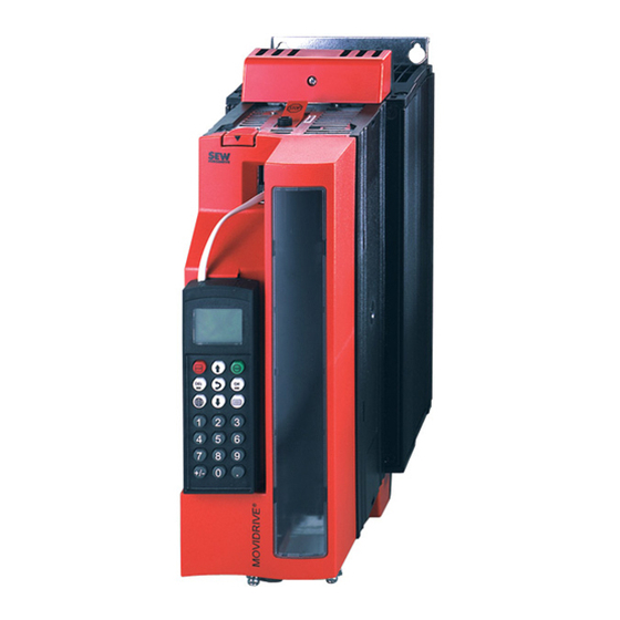
® Inspection and Maintenance of MOVIDRIVE Size 7 Unit design ® Inspection and Maintenance of MOVIDRIVE Size 7 INFORMATION Observe the permitted tightening torques (page 18) for any work on the unit Unit design The following figure shows the unit design of MOVIDRIVE MDX61B-503 (AC 400/500 V: 1600 / 2000 / 2500 [1] Phase module [2] Brake chopper module... -
Page 8: Replacing A Phase Module
® Inspection and Maintenance of MOVIDRIVE Size 7 Replacing a phase module Replacing a phase module Proceed as follows to replace a phase module: [6] 4x [4] 4x [5] 4x 2185987851 1. Loosen the 4 screws [4] of the upper cover [1] and remove it. 2. - Page 9 ® Inspection and Maintenance of MOVIDRIVE Size 7 Replacing a phase module [11] [10] 10x 2185989771 6. Remove the 10 screws [10] of the front panel [11] on the inverter coupling. Remove the cable rack [9] and the front panel [11]. To do so, lift the front panel [11] over the control unit towards you.
- Page 10 ® Inspection and Maintenance of MOVIDRIVE Size 7 Replacing a phase module [18] [15] [16] [17] [15] [16] [17] [12] [13] [14] 2185991691 7. Remove the 6 screws [14] of the UVW conductor rail bracket [13]. 8. Loosen the 3 screws [15] of the connection from the UVW conductor rails [12] to the phase modules.
- Page 11 ® Inspection and Maintenance of MOVIDRIVE Size 7 Replacing a phase module [19] [20] 6x 2185993611 11.Loosen the 6 retaining screws of the inverter coupling housing [19] on the phase modules. Remove the inverter coupling housing [19] with the printed circuit board and the control unit.
- Page 12 ® Inspection and Maintenance of MOVIDRIVE Size 7 Replacing a phase module [22] [21] [22] 2277501835 12.Loosen the 2 × 2 retaining screws of the lug at the phase module – DC link connec- tion. 13.Remove the 2 lower retaining screws [22] of the phase module [21] in the frame. Re- move the 2 upper retaining screws [22] of the phase module [21] in the frame.
-
Page 13: Replacing The Brake Chopper Module
® Inspection and Maintenance of MOVIDRIVE Size 7 Replacing the brake chopper module Replacing the brake chopper module INFORMATION When replacing the brake chopper module, adhere to the following process description and the drawings from chapters "Unit design" (page 7) and "Replacing a phase mod- ule"... -
Page 14: Replacing The Rectifier Module
® Inspection and Maintenance of MOVIDRIVE Size 7 Replacing the rectifier module Replacing the rectifier module INFORMATION When replacing the rectifier module, adhere to the following process description and the drawings from chapters "Unit design" (page 7) and "Replacing a phase module" (page 8). -
Page 15: Replacing The Fan Subassembly
® Inspection and Maintenance of MOVIDRIVE Size 7 Replacing the fan subassembly Replacing the fan subassembly Proceed as follows to replace the fan subassembly: 2276332683 1. Remove the phase, brake chopper or rectifier module [1]. 2. Unscrew the fan subassembly. 3. -
Page 16: Retrofitting The Brake Chopper Module
® Inspection and Maintenance of MOVIDRIVE Size 7 Retrofitting the brake chopper module Retrofitting the brake chopper module INFORMATION When retrofitting the brake chopper module, adhere to the following process descrip- tion and the drawings from chapters "Unit design" (page 7) and "Replacing a phase module"... -
Page 17: Conversion Into An It Network Unit
® Inspection and Maintenance of MOVIDRIVE Size 7 Conversion into an IT network unit Conversion into an IT network unit Size 7 is equipped with 2 "radio interference suppression" subassemblies [2], which are connected from +U to PE and from -U to PE. -
Page 18: Tightening Torques
® Inspection and Maintenance of MOVIDRIVE Size 7 Tightening torques Tightening torques Note the permitted tightening torques: Component Screws Tightening torque [Nm] [lb in] Cover screws M5 × 25 1,4 - 1,7 12 - 15 Screws with integral disk Conductor rail screws Insulating spacer M10 (SW32) Manual –... - Page 20 SEW-EURODRIVE—Driving the world SEW-EURODRIVE Driving the world SEW-EURODRIVE GmbH & Co KG P.O. Box 3023 D-76642 Bruchsal/Germany Phone +49 7251 75-0 Fax +49 7251 75-1970 sew@sew-eurodrive.com www.sew-eurodrive.com...
Need help?
Do you have a question about the Movidrive MDX60B and is the answer not in the manual?
Questions and answers