Table of Contents
Advertisement
Quick Links
Introduction
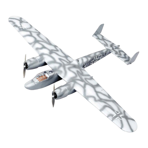
The following is a little history of the original development of this unique and handsome aircraft. The Dornier Do 217 was a later
development of the original Do 17 series of bombers and reconnaissance aircraft. The prototype Do 17 first flew in 1938 and was
not especially successful. Never-the-less development continued and early pre-production Do 217A-O's undertook a variety of
clandestine photo-recon missions over the Soviet Union, prior to the German attack in 1941. Further development of the type
produced the E-2 variant, originally conceived as a divebomber. However trials proved this unpractical and the E-2 was
ultimately used for bombing raids over Great Britain and for antishipping missions over the North Sea and the Atlantic.
Advertisement
Table of Contents

Subscribe to Our Youtube Channel
Related Manuals for SIG DORN IER Do 217


Summary of Contents for SIG DORN IER Do 217
- Page 1 Introduction The following is a little history of the original development of this unique and handsome aircraft. The Dornier Do 217 was a later development of the original Do 17 series of bombers and reconnaissance aircraft. The prototype Do 17 first flew in 1938 and was not especially successful.
-
Page 2: Reference Material
The SIG Do 217 is strictly a sport scale model and not necessarily based on any particular variant. Instead, we leaned on both the J-1 and 2R22 night fighter versions of this airplane to create our own R/C version. If you desire, the SIG Do 217 lends itself to a lot of details that would look great on this model. -
Page 3: Construction Overview
COMPLETE KIT PARTS LIST Balsa Sticks and Sheets 5 1/16"x3"x36" Balsa sheets for 4 1/16"x2"x36" Balsa sheets for wing 2 1/32"x3"x18" Balsa sheet for 2 1/16"x3/16"x36" Balsa sticks wing sheeting sheeting stabilizer sheeting for cap strips 2 1/4"x1/2"x24" Shaped balsa 1 3/32"x1"x36"... -
Page 6: Wing Construction
WING CONSTRUCTION Prepare the wing sheeting and spars. Cut 4 spars from the 1/8"x3/16"x24" (3.2x4.8x610mm) spruce 23-1/8" (587.4mm) long. Cut 4 spar doublers 7" (177.8mm) long from the 36" (914 mm) long piece of the same material. Glue a doubler to the top of each spar at one end then taper the last 2"... - Page 7 12. Glue one of the pre-shaped trailing edge sheets to the ribs and along the trailing edge and to the tip outline. To allow working time here it is best to use SIG-Bond glue to hold the top sheeting to the ribs and spars.
- Page 8 16. Plank the upper center section of the wings. Prepare the center section sheeting as shown in drawings. Fit the front piece first then cut the rear to fit in the remaining space. A neat trick to get the radius in the corner of the sheets is to trace around a quarter.
- Page 9 NOTE: We highly recommends that you use a speed control for each motor and place each control in the nacelle behind the motor. For this you will need to also cut a hole in the bottom of the tube just inboard of F-3 for the receiver lead of the speed control.
-
Page 10: Fuselage Construction
FUSELAGE CONSTRUCTION To make the assembly of the nacelle and fuselage assembly quicker and more efficient, pre-form the following parts so they can be drying while the stabilizer and rudders are built. 29. Secure parts numbered N-4 (4 pcs.), N-5 (4 pcs.), and N-6 (2 pcs.) from their laser cut sheets #8 and #9. 30. - Page 11 38. Cut two 3/8" (9.5 mm) from the end of each 1/8" (3.2 mm) pushrod tubes and insert these as pushrod bushings in the ribs in the four places shown on the plan. Slide a piece of 1/32" (.8 mm) music wire through the holes and bushings and align the bushings so the wire slides freely from side to side before...
- Page 12 48. Remove the elevators from the plan, sand them to the tapered shape and bevel the leading edge. 49. To make the elevator joiner and control horn, you will need the 3-1/2" (88.9mm) piece of 1/16" (1.5mm) music wire, the 1/16"...
- Page 13 NACELLE SURFACE CONSTRUCTION The nacelles are built similar to the fuselage and you can use them to master the shaping technique that will be used on the fuselage later. 57. Taper the last 3/8" (9.5mm) of the inside rear of each nacelle side. 58.
- Page 14 Optional Main Landing Gear Parts Required (not furnished) 2 - SIGSH596 Nose Wheel Strut 2 - SIGSH523 1/8" Landing Gear Clips 1 pair - KAV0098 2" Wheels 1 pkg. - SIGSH586 1/8" Wheel Collars Assembly Sequence 1. Build nacelles through to step 65. 2.
- Page 15 69. Glue on F-11, F-12, and the 1/4" (6.4 mm) square parts at the nose. 70. Glue in the 1/8"x1/4 " (3.2x6.4mm) stabilizer supports. 71. Glue in the 1/4" (6.4mm) square balsa wing hold down plate supports ahead of F-6 and below F-12. 72.
- Page 16 Optional Tail Wheel Installation Parts Required (not furnished) 1 - 1/32" Dia. x18" Music Wire 1 - 1/8" O.D. x18" Plastic Tube 1 - 1/16" Dia. x3-1/4" Music Wire 1 - SIGSH132 Tailwheel Bracket 2 - #4x1/2" Sheet Metal Screws 1 - 1/16"...
- Page 17 87. Glue the F-23's to the lower rear fuse from F-5 back. 88. With the 3/32"x1" (2.4x25.4mm) balsa strips glue the top rear corners in from F-6 to the tail. 89. Sand the top of the fuselage so that the sides between F-1 and F-2 are perfectly flat. 90.
-
Page 18: Airframe Assembly
100. Glue HF to the front of the hatch, centered on F-2. 101. There are four HS's on sheet #6. Bevel the bottom of one of these to sit flush on the hatch bottom and snug against F-3T. Now do the same for the other side. 102. - Page 19 110. Trial fit F-4T and dowel into place on F-4 making sure F-4T and F-4 are flush to each other. Remove F-4T, lay a sheet of waxed paper between it and F-4 in the wing saddle and replace F-4T. 111. Place the wing back into the wing saddle making sure the flat at the leading edge of the wing is flush with F-4T and the centerlines are in position.
- Page 20 119. Taper the rounded end of the WFT top so it blends into the top of the wing and glue it onto the top of F-6T and onto the centerline of the wing. 120. Sand a 45 deg. angle along the sides of WFT to match former F-6T.
- Page 21 Installing Easy Hinges SIG’s famous Easy Hinges have been included in your kit to hinge all of the control surfaces. Each ultra-thin hinge is actually a three-part laminate - a tough plastic inner core sandwiched by an absorbent wicking material. The hinges have been chemically treated to slow down the reaction to thin CA glue (normally instant), to allow the glue time to soak all the way to the ends of the hinge and into the surrounding wood.
- Page 22 This should free up their movement. Continue flexing the elevators until they can be easily moved. Any excess CA glue can be easily removed with SIG Debonder. 137. In order to install the stabilizer, the top of the fuselage behind F-9 needs to be removed.
- Page 23 142. Fit the fuselage top back over the stabilizer, trim the covering on the top of the stabilizer, then glue the top down. Sand and fill as needed to blend into fuselage top. 143. Fill-in any dents or dings as required, followed by finish sanding the fuselage. 144.
- Page 24 153. Finish covering the model in your chosen color scheme. COVERING TIPS: It helps your covering job if you brush some SIG 154. Detail the cockpit at this time. The instrument panel is copied from pictures of the STIX-IT over the concave areas full sized aircraft and is included on a separate sheet inserted in the manual.
- Page 25 3/32" (2mm) of the point filed off. 161. Hinge the ailerons to the wing using three SIG Easy Hinges for each aileron, as shown on the plans. 162. Plug an aileron servo into a pre-installed servo extension, tape or heat shrink the plugs together and feed this back down the paper tube to the hole in the center of the wing before screwing the servo into its mount.
-
Page 26: Decal Application
FLYING The SIG Do 217 is actually quite easy to fly, provided you've had previous experience and success in flying R/C models in the past. This model is not recommended as an R/C trainer. If this is your first R/C model aircraft, we urge you to seek out and use an experienced R/C pilot to pre-flight, test fly, and flight-trim the model for you. - Page 27 Before making the first test flight, take the time to make sure each of the flight control surfaces are moving in the correct directions and are properly centered. Once you're certain that they are, check these controls, once again. Next, holding the model securely, throttle-up the motors to make sure they're reaching full power and sound in "synch".
- Page 28 We sincerely hope that you have enjoyed building and flying your new SIG Do 217 model. We also hope that you will continue to fly it safely for a long time to come, with respect for other people and property.
Need help?
Do you have a question about the DORN IER Do 217 and is the answer not in the manual?
Questions and answers